
Routing in a packet switching network with mobile terminals

a packet switching network and mobile terminal technology, applied in the direction of data switching by path configuration, wireless network protocols, electrical devices, etc., can solve the problems of address exhaustion (the inability to re-use an address), additional mobility cost, and cost of tunnelling, so as to achieve convenient and reliable

Inactive Publication Date: 2007-01-09
BRITISH TELECOMM PLC
View PDF49 Cites 55 Cited by
  • Summary
  • Abstract
  • Description
  • Claims
  • Application Information

AI Technical Summary

Benefits of technology

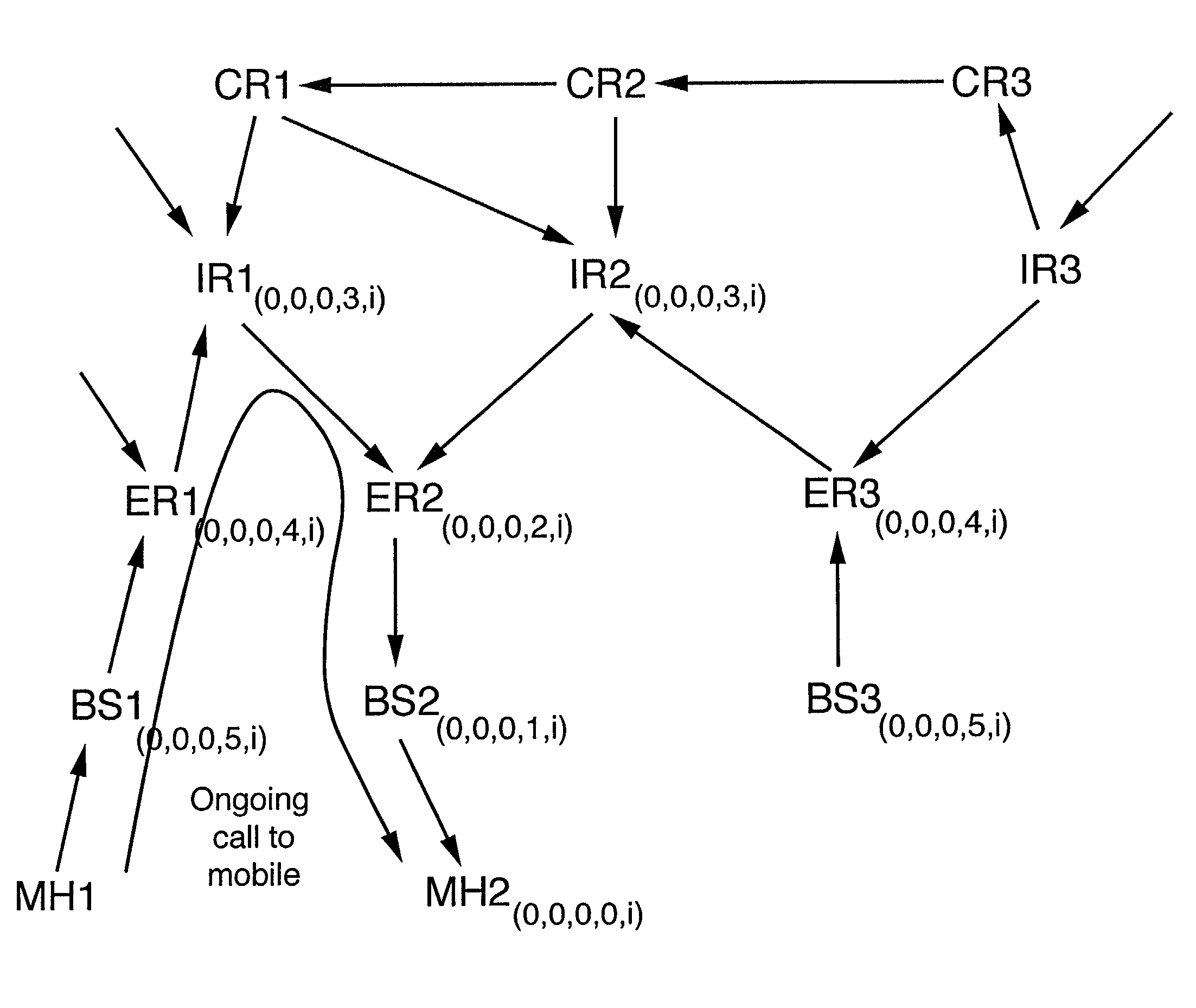
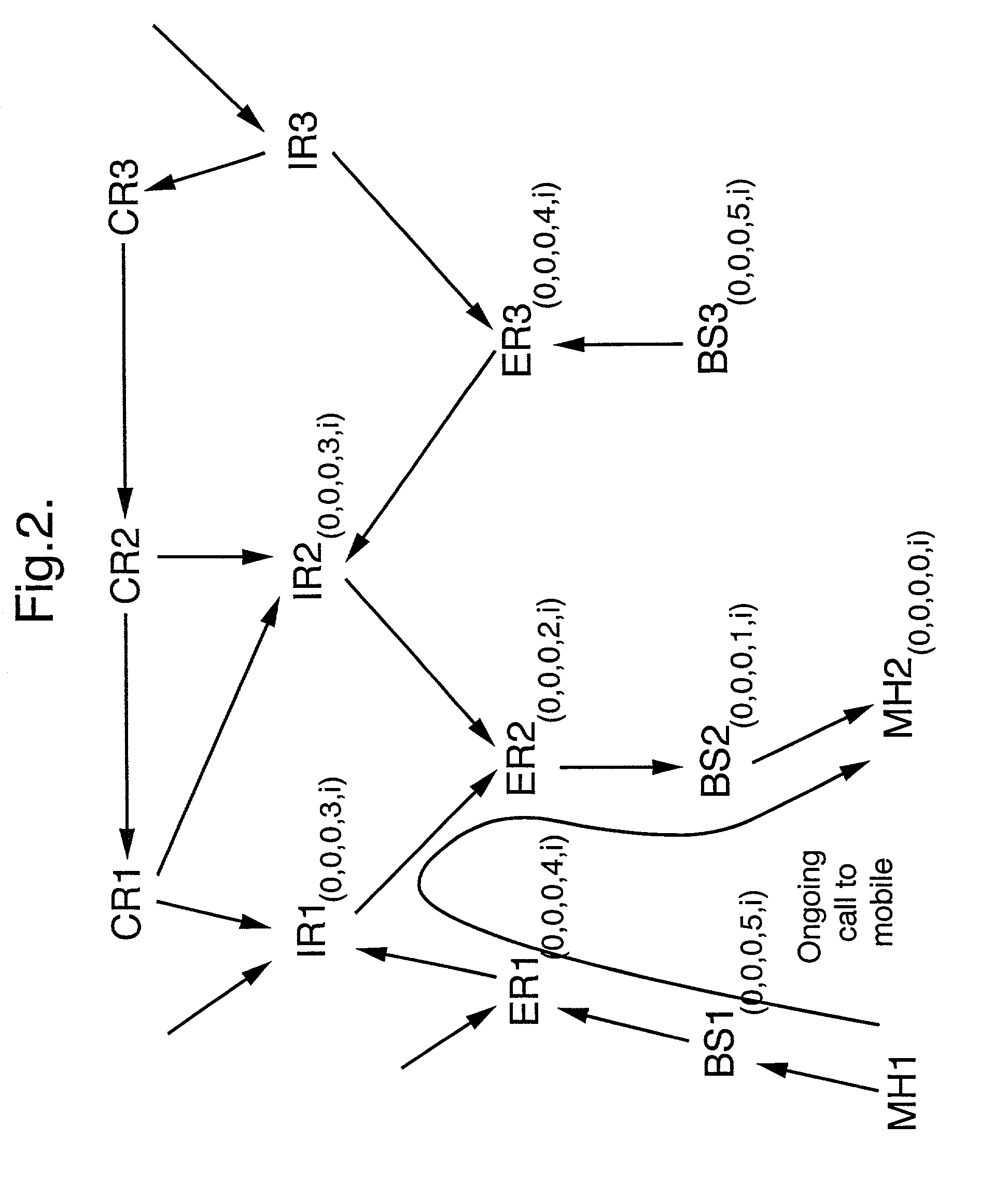
[0022]By returning the routing to the first access node and transmitting a routing message to the first access node indicating that it may re-allocate the home address when it becomes free, the need for a separate address attendant, which requires frequent updating due to changes in routing, may be avoided.
[0026]This aspect provides a convenient and yet reliable way of altering routing in the infrastructure for the first network address, when a plurality of routing paths in the infrastructure are directed to a single access node for the first network address.

Problems solved by technology

The additional cost of mobility is the provision of this Home Agent / Foreign Agent interface, and especially with packet systems, the cost of tunnelling (forwarding messages from one address to another), address exhaustion (the inability to re-use an address from which forwarding is taking place) and triangular routing.
Drawbacks with the HAWAII proposals include the concentration of Mobile IP tunnels in few nodes in the core of the network, the domain root routers, such that failure of any of these nodes may result in large-scale failure of all Mobile IP state and associated sessions handled by the failing node.
Furthermore, since all routing from outside the home domain into the home domain, and in the reverse direction, must occur via the home domain root router, failure of the home domain root router may also result in large-scale failure.
A disadvantage is that the routing signalling load is high, particularly when large numbers of mobile units are active in the network.
This again increases routing signalling load in the network.

Method used


Image

  • Routing in a packet switching network with mobile terminals
  • Routing in a packet switching network with mobile terminals
  • Routing in a packet switching network with mobile terminals

Examples


Embodiment Construction

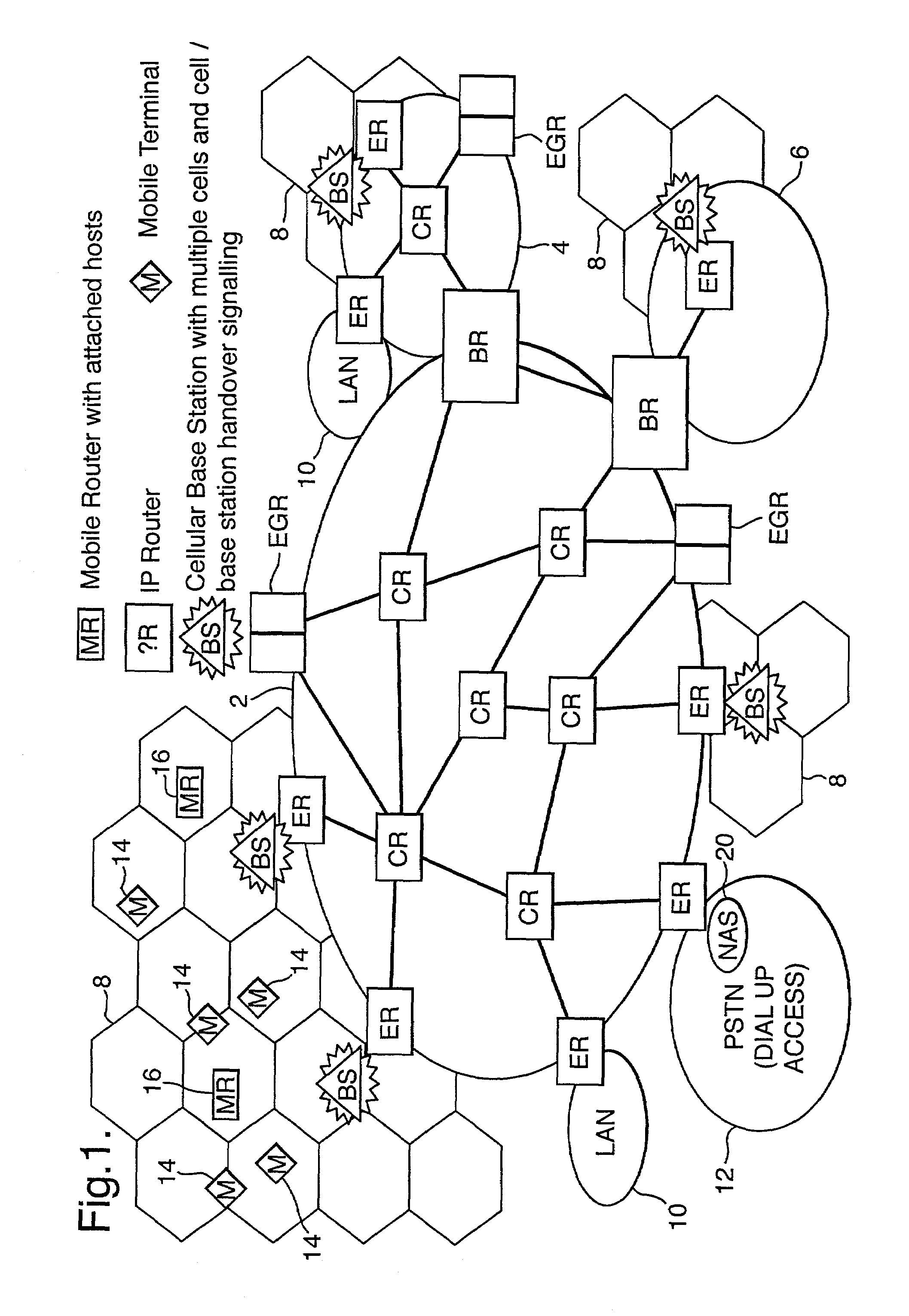
[0034]Referring now to FIG. 1, an example of a fixed / mobile topology in accordance with an embodiment of the present invention is shown. The topology includes, by way of example, three packet switching networks 2, 4, 6 forming an Autonomous System (AS). One Definition given for the term Autonomous System, is “a set of routers and networks under the same administration” (“Routing in the Internet”, Christian Huitema, Prentice-Hall, 1995, page 158). Herein the Autonomous System, as referred to as a routing domain in the art, is also intended to mean a network, or a set of networks, having routers running the same routing protocol. An Autonomous System may be connected to other Autonomous Systems forming a global internetwork such as the Internet (used by way of example hereinafter). The routing protocol is an interior gateway protocol, and communications with other Autonomous Systems are achieved via exterior gateway protocols such as the Border Gateway Protocol (BGP). Examples of know...


PUM


Abstract

Packets in a packet switching network are routed along a routing path defined by data held in packet switching nodes. One or more network addresses are assigned to a first access node as home addresses. A first home address is allocated to a first mobile node with at least one routing path being directed to a first access node for that first home address. Routing in the packet switched infrastructure is altered when the first mobile node receives service from a second access node by transmitting routing update messages to a limited subset of localized packet switching nodes such that at least one routing path in the infrastructure is directed to the second access node for the first home address. Routing in the infrastructure is subsequently altered such that at least one routing path is directed to the first access node for the first home address, and the first home address is allocated to a second mobile node served by the first access node.

Description

[0001]This application is the US national phase of international application PCT / GB00 / 02769 filed Jul. 19, 2000 which designated the U.S.BACKGROUND[0002]1. Technical Field[0003]This invention relates to the routing of telecommunications signals. More particularly it relates to a method of routing such signals to both fixed and mobile telecommunications mediums, such that similar services can be used in the same way by users on either medium, and to allow system operators to reduce costs by greater commonality of switching and other network-based facilities. The present invention is concerned with the routing of packet-based communications such as those used in the “Internet” using the so-called “Internet Protocol” (IP).[0004]2. Related Art[0005]Present mobile medium systems are arranged such that a mobile user and associated systems collaborate at the interface with the network (typically the radio base station) to enable a mobile node to change from communicating with one base stat...

Claims


Application Information

Patent Timeline
IPC IPC(8): H04L29/06H04L12/28H04L45/02H04W8/08H04W8/26H04W40/02H04W40/24H04W40/36H04W80/04
CPCH04L29/12216H04L29/12301H04L29/12311H04L45/02H04L61/2007H04L61/2076H04W8/087H04W40/02H04L61/2084H04W80/04H04L2212/0025H04W8/26H04W40/248H04W40/36H04L2212/00H04L61/5007H04L61/5076H04L61/5084
Inventor O'NEILL, ALAN WCORSON, MATHEW S
Owner BRITISH TELECOMM PLC
Learn More