

Image heating apparatus
a heating apparatus and image technology, applied in the field of image heating apparatus, can solve the problems of deterioration of heat transfer efficiency, drawback of increased heating cost, and deterioration of components, and achieve the effect of satisfactory fixing ability and fast start-up tim
- Summary
- Abstract
- Description
- Claims
- Application Information
AI Technical Summary
Benefits of technology
Problems solved by technology
Method used
Image

Examples
first embodiment
(First Embodiment)
(1) Example of Image Forming Apparatus
[0040]FIG. 5 is a schematic view showing a configuration of an image forming apparatus employing an image heating apparatus of the present invention. The image forming apparatus of this example is a color laser printer utilizing an electrophotographic process of an intermediate transfer belt type.
a) Full Color Mode
[0041]A photosensitive drum 101, constituting an image bearing member, is rotated counterclockwise, as indicated by an arrow, by unillustrated drive means, and is uniformly charged in a predetermined potential of a predetermined polarity by a primary charger 102.
[0042]Then it is subjected to a laser scanning exposure L by an exposure apparatus (laser scanner) 103 whereby an electrostatic latent image is formed corresponding to an image pattern of a yellow component of a full-color image.
[0043]As the photosensitive drum 101 is rotated further, developing apparatuses 104a, 104b, 104c and 104d supported by a rotary suppo...
second embodiment
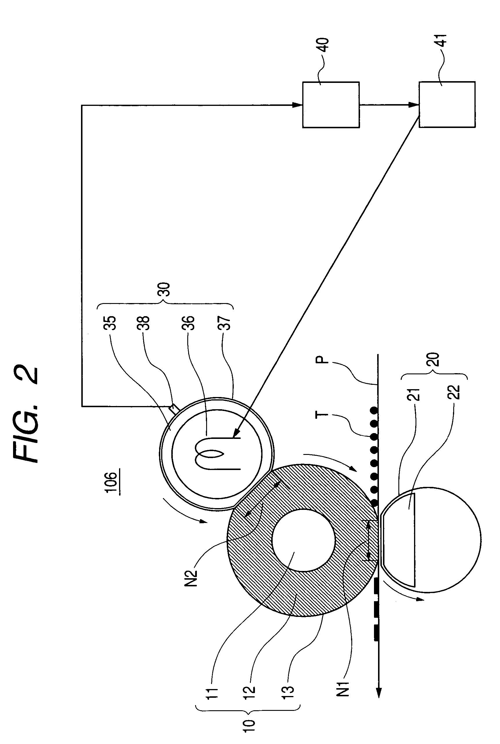
(Second Embodiment)
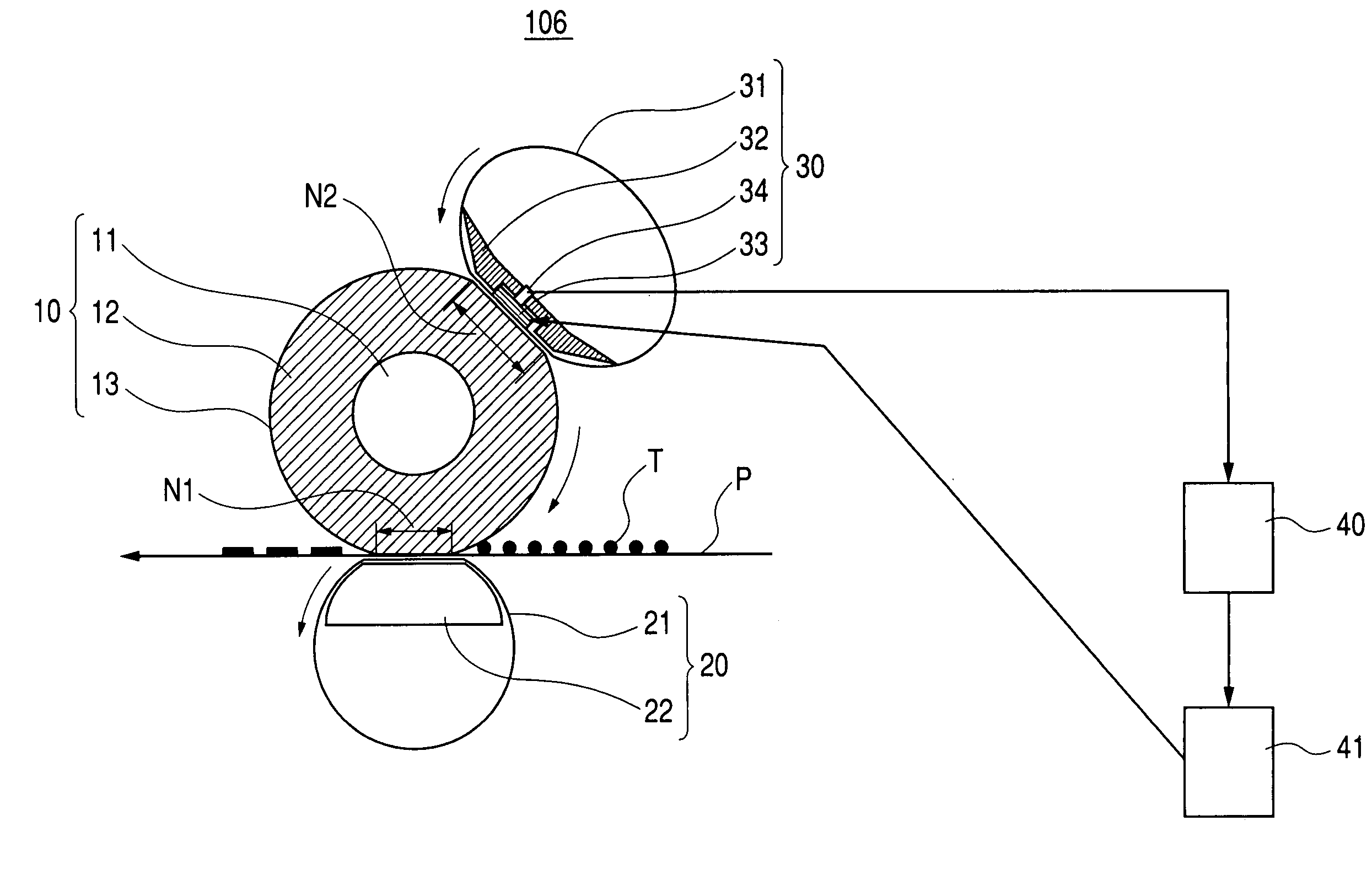
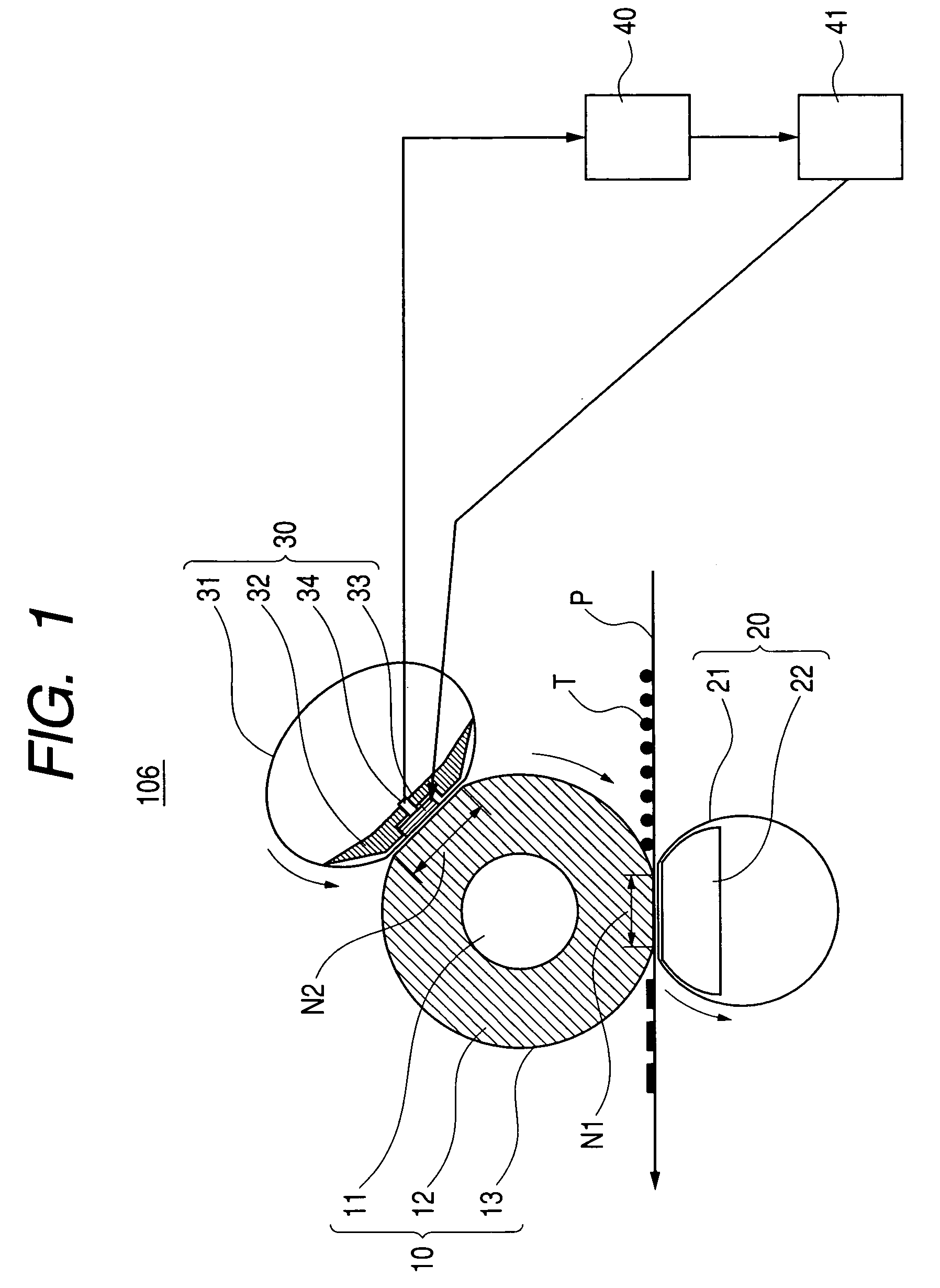
[0080]FIG. 2 shows a second embodiment. A configuration of the image forming apparatus, including the heat fixing apparatus of the present embodiment, is same as that of the first embodiment, explained in FIG. 5, and will not, therefore, be explained. The present embodiment corresponds to the heat fixing apparatus 106 shown in FIG. 5, of which details will be explained with reference to FIG. 2. In the following, components same as or equivalent in function to those in FIG. 1 are represented by same numbers and are omitted from explanation.
[0081]The fixing apparatus 106 of the present embodiment is characterized in that the heat supply means 30 is constituted of a heat roller (non-flexible rotary member). The fixing roller 10 and the back-up means 20 have a configuration same as that in the first embodiment.
[0082]The heat roller 30 constituting the heat supply means is provided with a heat-generating member 36 such as a halogen lamp inside a hollow metal core 35 of...
third embodiment
(Third Embodiment)
[0087]FIG. 3 shows a third embodiment. A configuration of the image forming apparatus, including the heat fixing apparatus of the present embodiment, is same as that of the first embodiment, explained in FIG. 5, and will not, therefore, be explained. The present embodiment corresponds to the heat fixing apparatus 106 shown in FIG. 5, of which details will be explained with reference to FIG. 3. In the following, components same as or equivalent in function to those in FIG. 1 are represented by same numbers and are omitted from explanation.
[0088]The fixing apparatus 106 of the present embodiment is featured in employing heat supply means 30 of electromagnetic induction heating type. The heat supply means 30 is constituted in the fixing apparatus of the first embodiment, by modifying the ceramic heater constituting the heater 33 of the heat supply means 30 to an induction heat-generating member 33a such as an iron plate, and by providing an excitation coil 42 and a ma...
PUM
 Abstract
Description
Claims
Application Information