Magnetic mounting assembly

a technology of mounting assembly and magnetic field, which is applied in the direction of machine supports, furniture parts, couplings, etc., can solve the problems of limiting the range of positions in which the camera can ultimately be fixed, unnecessarily complicated maneuvering of multiple component structures, and limiting the range of positions

Inactive Publication Date: 2007-01-16
OMPS JUSTIN T
View PDF16 Cites 66 Cited by
  • Summary
  • Abstract
  • Description
  • Claims
  • Application Information

AI Technical Summary

Benefits of technology

[0010]It is a primary object of the present invention, therefore, to overcome the disadvantages of the prior art and to provide a simple magnetic mounting assembly that will securely hold a positionable object on a supp

Problems solved by technology

Mounting an object that is required to be positioned and fixed in a potentially infinite number of locations on a support in a manner that provides stable and secure attachment while allowing universal positioning of the mounted device has long been a challenge.
This arrangement would be likely to be limited to use with relatively light weight cameras.
This multiple component structure requires unnecessarily complicated maneuvers to move the ball so the camera is fixed in the desired position and then to insure that the camera is held in this position.
The nonspherical shape of the ball, however, limits the range of positions in which the camera can ultimately be fixed, and the effective frictional forces will be reduced as the components of this apparatus, particularly the O ring, are subject to wear.
Since the bearing housing does not support the ball in a receptacle having a corresponding radius of curvature, the range of movement of the ball, and thus the camera, is limited by this structure.
Although this arrangement provides a secure and stable support for the camera, it does not permit universal movement of the camera relative to the support.
The arrangement described

Method used


Image

  • Magnetic mounting assembly
  • Magnetic mounting assembly
  • Magnetic mounting assembly

Examples


Embodiment Construction

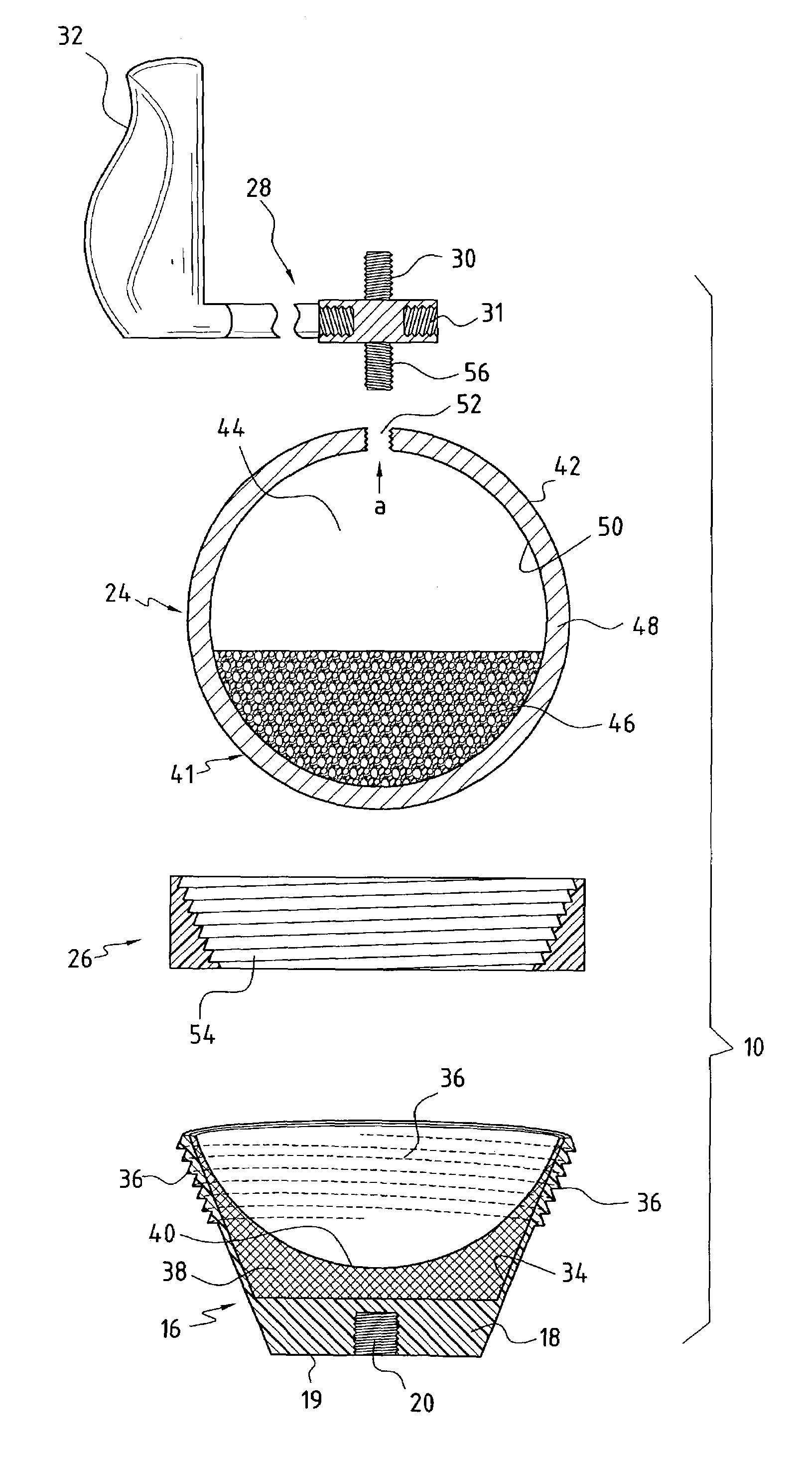
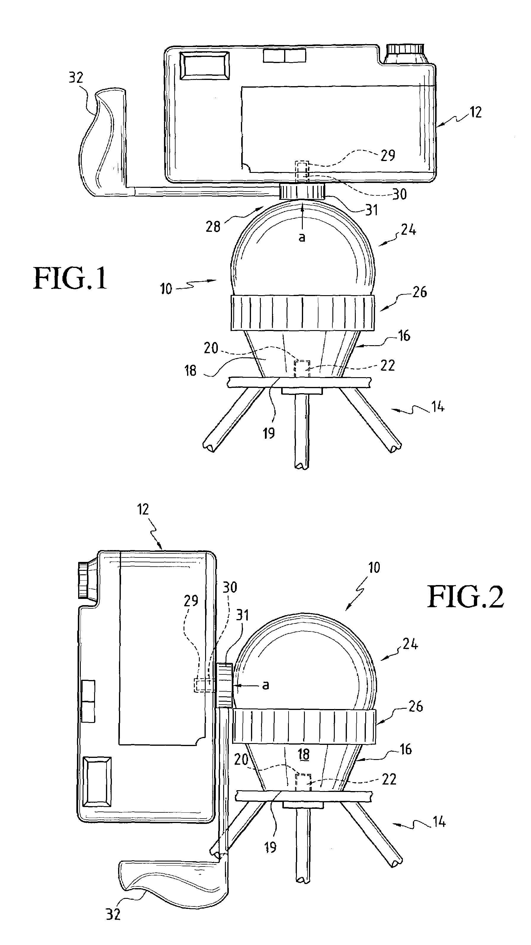
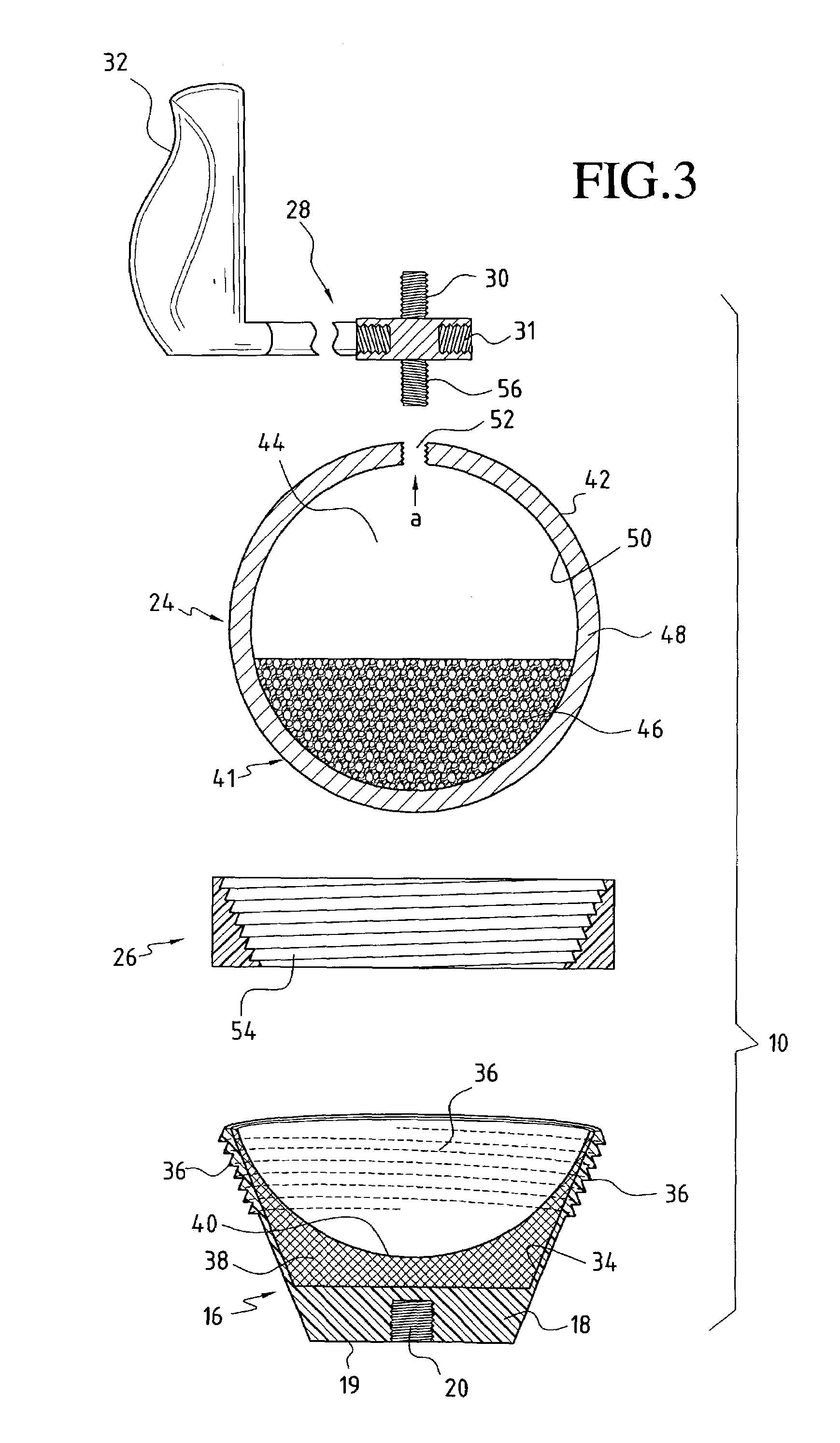
[0028]Conventional mechanisms for supporting, holding and positioning positionable objects have frequently involved complex rather than simple construction and have not always functioned to concurrently support and position the positionable object as effectively as might be desired. Once the supported positionable object is positioned, moreover, the holding function of these mechanisms often requires extensive adjustment and does not always insure that the the positionable object will be held securely in place in the desired position. The mounting assembly of the present invention presents a simple structure that efficiently and effectively provides a secure and stable attachment between a support and a positionable object to be variably fixed in one of a desired range of infinite positions and held in the desired selected position on the support. The mounting assembly of the present invention employs frictional and magnetic forces to effect smooth rapid movement of the supported po...


PUM


Abstract

A magnetic mounting assembly for securely attaching a positionable object to be variably fixed in a desired selected position to a support, for universally moving the positionable object to the desired selected position, and for holding the positionable object in that position during operation is provided, including a positioning element with a ball that is attached to the positionable object. A support element includes a socket configured to movably engage the ball. One of either the ball or socket includes a magnetic material and the other includes a magnetically attractive material to hold the ball in the socket by magnetic as well as frictional forces. An adjustment collar controls the axial movement of the ball to increase or decrease the magnetic force holding the ball in the socket. This mounting assembly is particularly useful for supporting a camera on a tripod.

Description

TECHNICAL FIELD[0001]The present invention relates generally to mounting structure intended to movably mount and position a positionable object on a support and specifically to a magnetic mounting assembly designed to support and universally position a wide range of sizes and weights of positionable objects, including cameras or like devices on tripods or other supporting structure.BACKGROUND OF THE INVENTION[0002]Mounting an object that is required to be positioned and fixed in a potentially infinite number of locations on a support in a manner that provides stable and secure attachment while allowing universal positioning of the mounted device has long been a challenge. Over the years the prior art has proposed a number of solutions to this problem, particularly with respect to the positioning of cameras on tripods or other supports. U.S. Pat. No. 318,480 to Kendrick, for example, discloses a joint structure between a camera and tripod that enables the camera to be universally adj...

Claims


Application Information

Patent Timeline
IPC IPC(8): F16M11/02A47G5/00F16C11/06F16M11/14
CPCF16C11/0619F16M11/041F16M11/14F16M13/00Y10T403/32631Y10T403/32196Y10T403/32311Y10T403/32032Y10S403/01
Inventor OMPS, JUSTIN T.
Owner OMPS JUSTIN T
Why Eureka
Try Eureka