Road indication device

a technology of indication device and arrow sign, which is applied in the direction of fixed installation, lighting and heating apparatus, instruments, etc., can solve the problems of inability to provide sufficient guiding indication, decreased visbility of arrow sign, and glare of disabled objects, so as to improve the visibility of light pillar, easy to identify, and easy to indicate

Inactive Publication Date: 2007-01-16
TOSHIBA LIGHTING & TECH CORP
View PDF4 Cites 13 Cited by
  • Summary
  • Abstract
  • Description
  • Claims
  • Application Information

AI Technical Summary

Benefits of technology

[0010]According to the foregoing description, an object of this invention is to provide a road indication device and an irradiation device capable of improving the visibility in the bad weather for precisely guiding and indicating the position of the road.

Problems solved by technology

However, when the weather is bad such as snowfall, etc., the snow under the covered area of the road lamp is irradiated to create a light curtain, so that disability glare might occur.
However, when the weather is bad such as snowstorm, the visbility of the arrow sign is decreased, sufficient guiding indication is impossible.
In addition, the color of the laser beam is restricted and a suitable color for better visibility cannot be selected.
Therefore, there is a problem that the degree of freedom of selecting the light color is small.
To obtain a light with sufficient visibility in the bad weather, such as, the snowfall using the laser beam, a huge laser device is required and therefore expensive.
Therefore, it is very difficult to set the laser device providing sufficient light together with the arrow sign on the road.
In addition, because the laser irradiation device is set outdoors, people might gaze the laser irradiation device and thereby adversely affecting human eyes.

Method used


Image

  • Road indication device
  • Road indication device
  • Road indication device

Examples


first embodiment

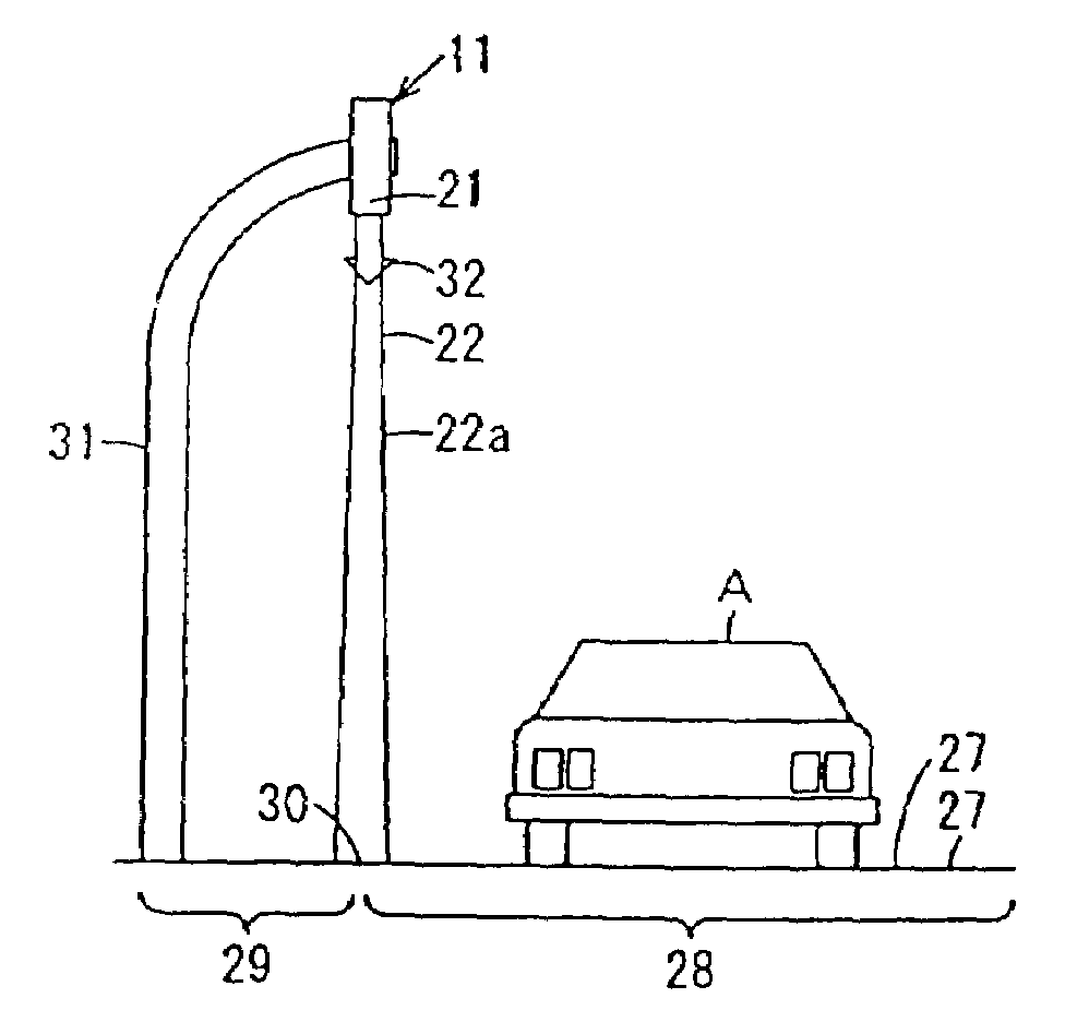
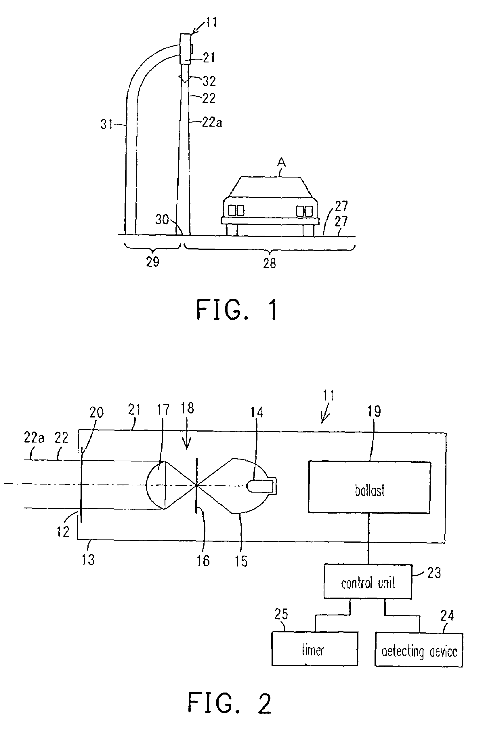
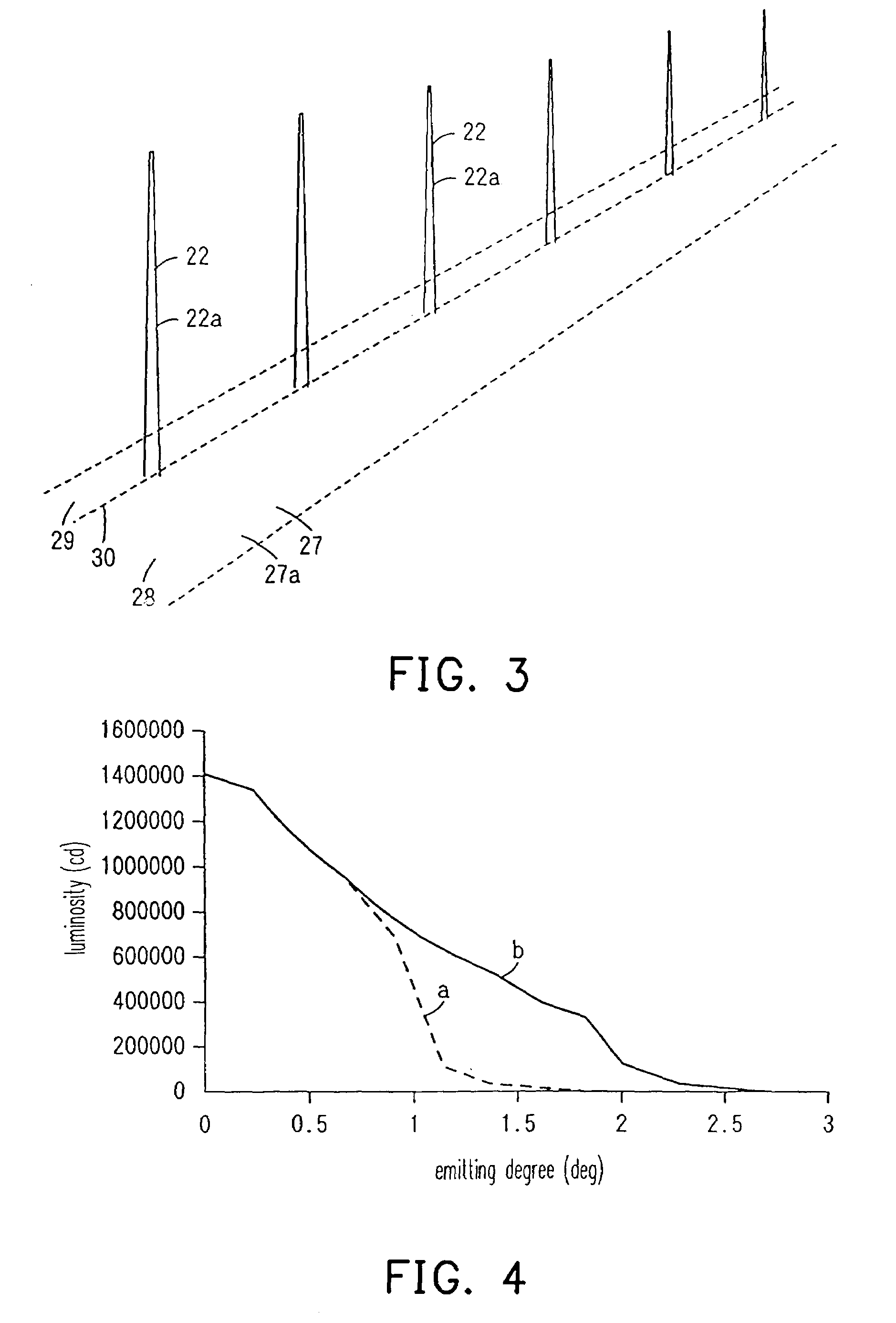
[0079]The embodiments according to the present invention will be described in detail accompanying with the attached drawings. FIG. 1 to FIG. 5 illustrate the views of a road indication device according to the first embodiment according to the invention. FIG. 1 is a diagram showing a use status of a road indication device, FIG. 2 is a block diagram showing a structure of the road indication device, FIG. 3 is a diagram showing a use status where the road indication devices are set at a predetermined distance on the road, FIG. 4 is a graph showing a light distribution of the road indication device, and FIG. 5 shows status at vertical angles of 90° and 80° relative to the road indication device.

[0080]As shown in FIG. 2, the road indication device 11 comprises a case 13 with a light projection opening 12 for projecting the light at one end along a light axis. A lamp 14, i.e., an HID (high intensity discharge) lamp such as a metal halide lamp, a halogen lamp, an ultra high pressure mercur...

second embodiment

[0106]FIG. 6 shows a road indication device according to the second embodiment of the present invention. As shown in FIG. 6, by bending a reflection portion 32a from the edges of an arrow portion at the lower end of the arrow sign 32 to a surface where the light 22 is irradiated there to, the reflection light reflected by the reflection portion 32a is irradiated to the surface of the arrow sign 32. As a result, the arrow sign 32 becomes brighter and the visibility can be further improved.

[0107]In addition, the light projection direction of the light 22 of the road indication device 11 can be constructed to alternatively move between the direction of the pavement 27a and the direction of the arrow sign 32 based on the time zone, etc. under the control of the control unit 23. For example, the light 22 of the road indication device 11 is usually projected towards the pavement 27a of the road 27, and projected towards the arrow sign 32 in the late-night time zone when the traffic is sma...

third embodiment

[0108]FIG. 7 shows a road indication device according to the third embodiment of the present invention. As shown in FIG. 7, the arrow sign 32 comprises a long base 34 extending in an up-and-down direction and a arrow portion 35 that is substantially triangular and connected to the lower end of the base 34. The long base 34 and the arrow portion 35 are bent to a convex surface that the central portion of the face opposite to the face where the light projection unit 21 is installed thereon is convex.

[0109]On the face where the light projection unit 21 of the base 34 is installed, a rail 27 with a groove 36 is installed along the up-and-down direction. Link means 38, including bolts, formed at two locations (up and down) on the side face of the light projection unit 21 is slidably engaged and fixed to the groove 36 of the rail 37. Therefore, the position of the arrow sign 32 can be adjusted up and down with respect to the light projection unit 21. Installation metal fittings 39 are ins...


PUM


Abstract

A road indication device is provided. The road-guidance indicating device has a light projection unit including light control means for controlling a lamp and light emitted from the lamp. The light projection unit project a light whose peak luminosity is 30000 cd or more, i.e., the light has a luminosity equal to or larger than a peak luminosity of a headlight of a car running on the road. Since a light pillar of light having a high light output and a thick light pillar is projected from the light projection unit, the visuality of the light pillar is improved even in the bad weather and the boundary between the driveway and the shoulder on the road can be affirmatively guided and indicated.

Description

CROSS-REFERENCE TO RELATED APPLICATION[0001]This application claims the priority benefit of Japanese application serial no. 2003-142006, 2003-170710, 2003-172358, 2003-338315 & 2004-014644, respectively filed on May 20, 2003, Jun. 16, 2003, Jun. 17, 2003, Sep. 29, 2003 & Jan. 22, 2004.BACKGROUND OF THE INVENTION[0002]1. Field of the Invention[0003]This invention relates in general to a road indication device for guiding and indicating positions on the road by light.[0004]2. Description of Related Art[0005]Generally, the road lamps for illuminating the road are lit according to the surrounding brightness to illuminate a predetermined range of the road. However, when the weather is bad such as snowfall, etc., the snow under the covered area of the road lamp is irradiated to create a light curtain, so that disability glare might occur.[0006]In addition, at snowbound area, when the boundary between the road and the shoulder is buried by the fallen snow, the boundary might not be distinc...

Claims


Application Information

Patent Timeline
Patent Type & Authority Patents(United States)
IPC IPC(8): B60Q1/26F21S8/00F21V7/00G09F19/18
CPCG09F19/18
Inventor KOJIMA, HIROYUKIISHIWATA, TOMOKOICHIJO, TAKASHIOGAWA, KOZOTAKANO, YASUHARU
Owner TOSHIBA LIGHTING & TECH CORP
Why Eureka
Try Eureka