Golf club grip with embedded display and method of fabrication

Inactive Publication Date: 2007-01-16
DOWNEY PHILIP L
View PDF19 Cites 6 Cited by
  • Summary
  • Abstract
  • Description
  • Claims
  • Application Information

AI Technical Summary

Benefits of technology

[0015]A further very important advantage of the invention is that limited runs of grips having different display features can be performed and alternated with runs of grips having other display features without the lengthy mold down time and lost production time that would otherwise be required to produce grips having different display features. To the contrary, by the utilization of different placards having different raised displays formed thereon, changes in the display features may be accomplished utilizing the same mold equipment with different, unique placards incorporated in the grip structure.
[0016]A further very advantageous feature of the invention is that very fine detail in mold display features can be achieved by embedding placards containing the fine detail required from a common set of molds, without the necessity for constructing intricate socket molds for each different display desired.
[0017]In one broad aspect the present invention may be considered to be an implement grip having a hollow inner socket, a placard, and a jacket that encapsulates the socket and portions of the placard. The socket is a hollow structure having inner and outer surfaces and formed of a thermoplastic material having an open end for receiving a handle of an implement and an opposite end. The socket has a wall structure with a plurality of locating apertures defined in the outer surface of the wall. The placard is formed with a mounting base having inner and outer surfaces and with flow openings defined therethrough. The placard includes at least one raised display projecting from its outer surface. The display has an outer face. The placard further includes a plurality of positioning pegs projecting from the inner surface of the mounting base. The positioning pegs are inserted into the locating apertures in the socket. In this way the placard is mounted on the outer surface of the socket. The jacket is formed with an outer surface of a thermoplastic material molded upon the socket and encapsulating the mounting base of the placard. The jacket laterally surrounds the display. In this way the mounting base is totally concealed and the display is laterally surrounded by the

Problems solved by technology

However, with use, portions of the paint very typically flake off so that the portion remaining presents an unsightly, unflattering appearance.
However, even though the system produces a very superior product, there are certain manufacturing difficulties.
Changing of the molds is time consuming, as there are inevitably delays in adjusting and fine tuning the molding machinery each time a different socket mold is installed into the molding apparatus.
The resulting d

Method used


Image

  • Golf club grip with embedded display and method of fabrication
  • Golf club grip with embedded display and method of fabrication
  • Golf club grip with embedded display and method of fabrication

Examples


Embodiment Construction

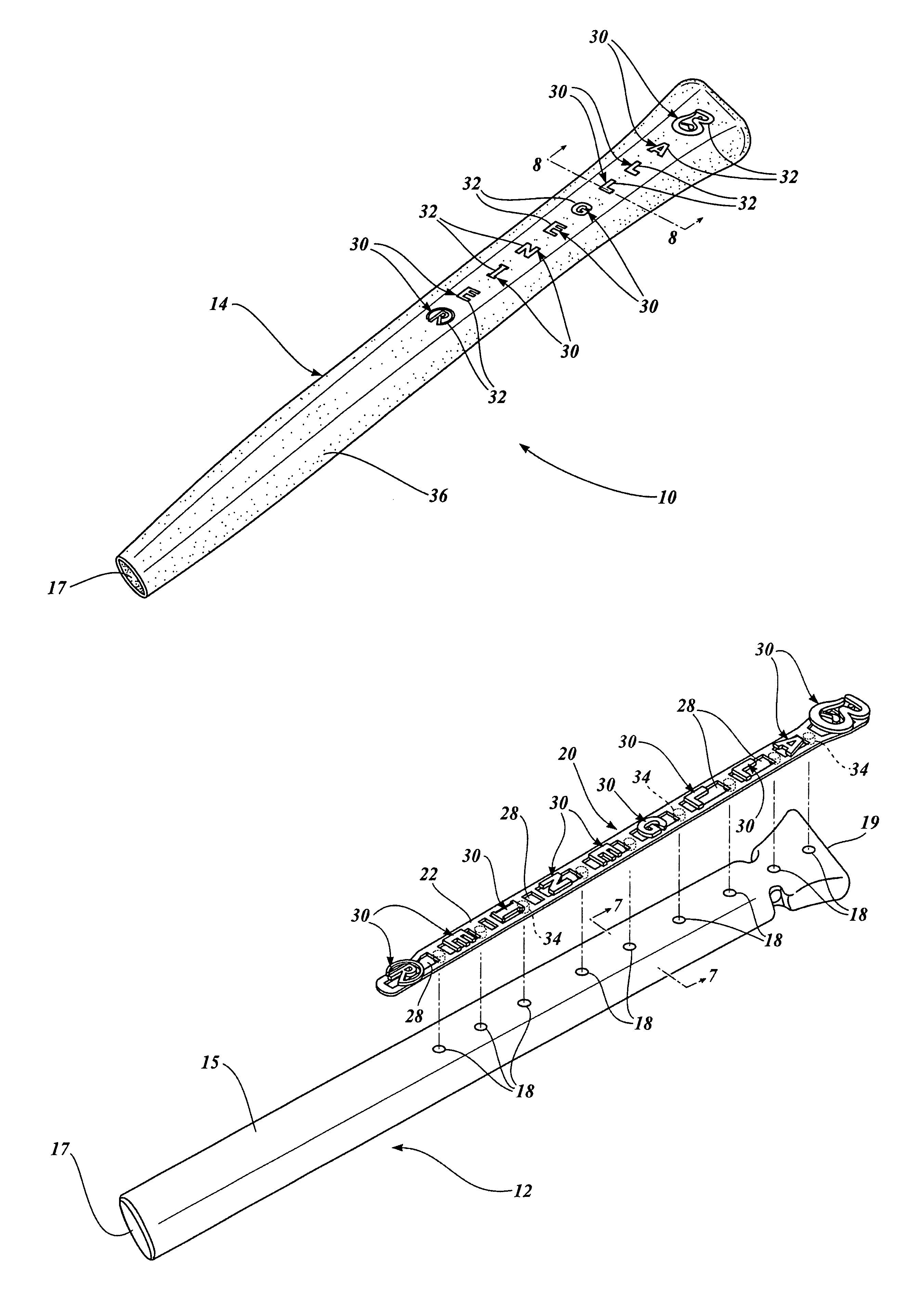
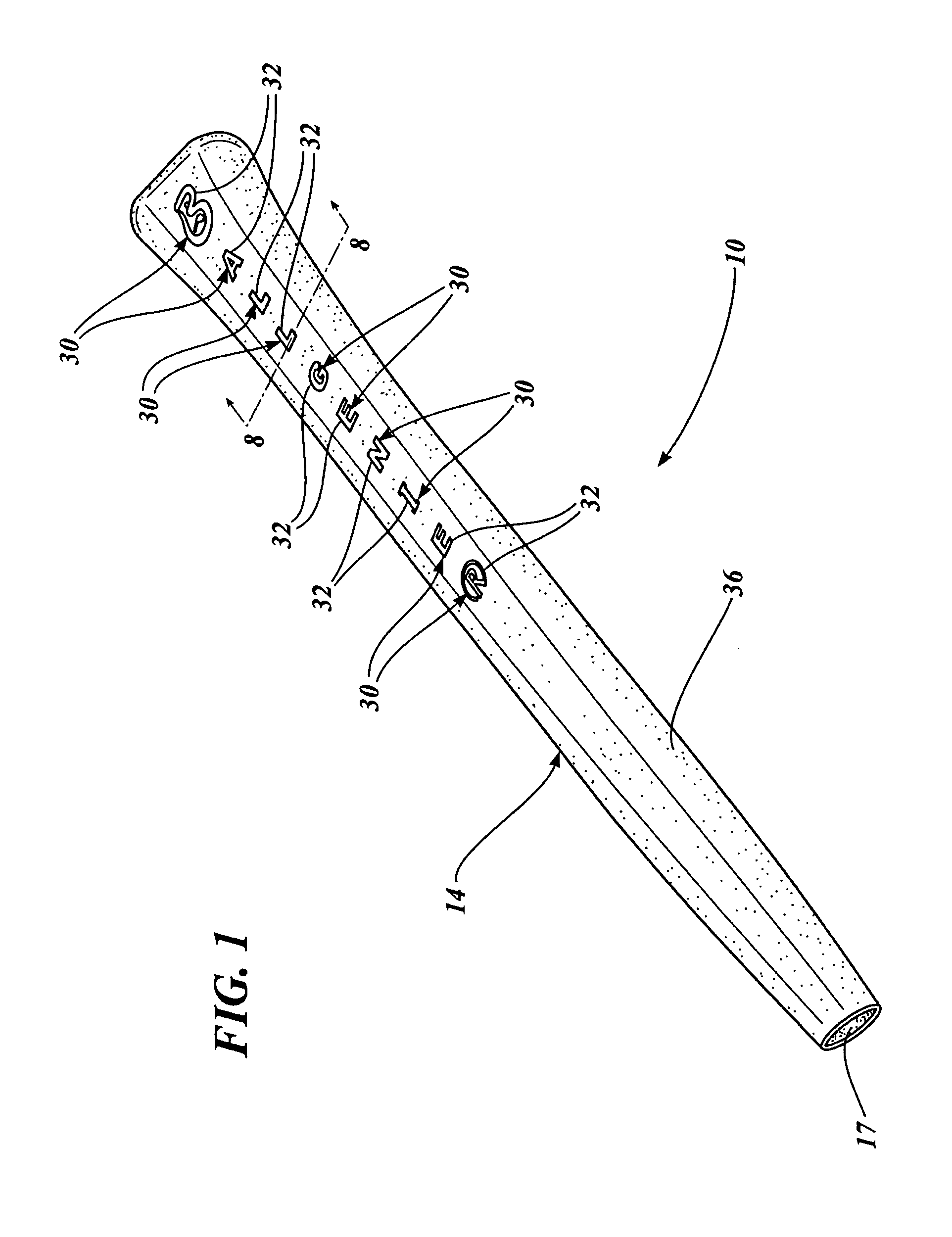
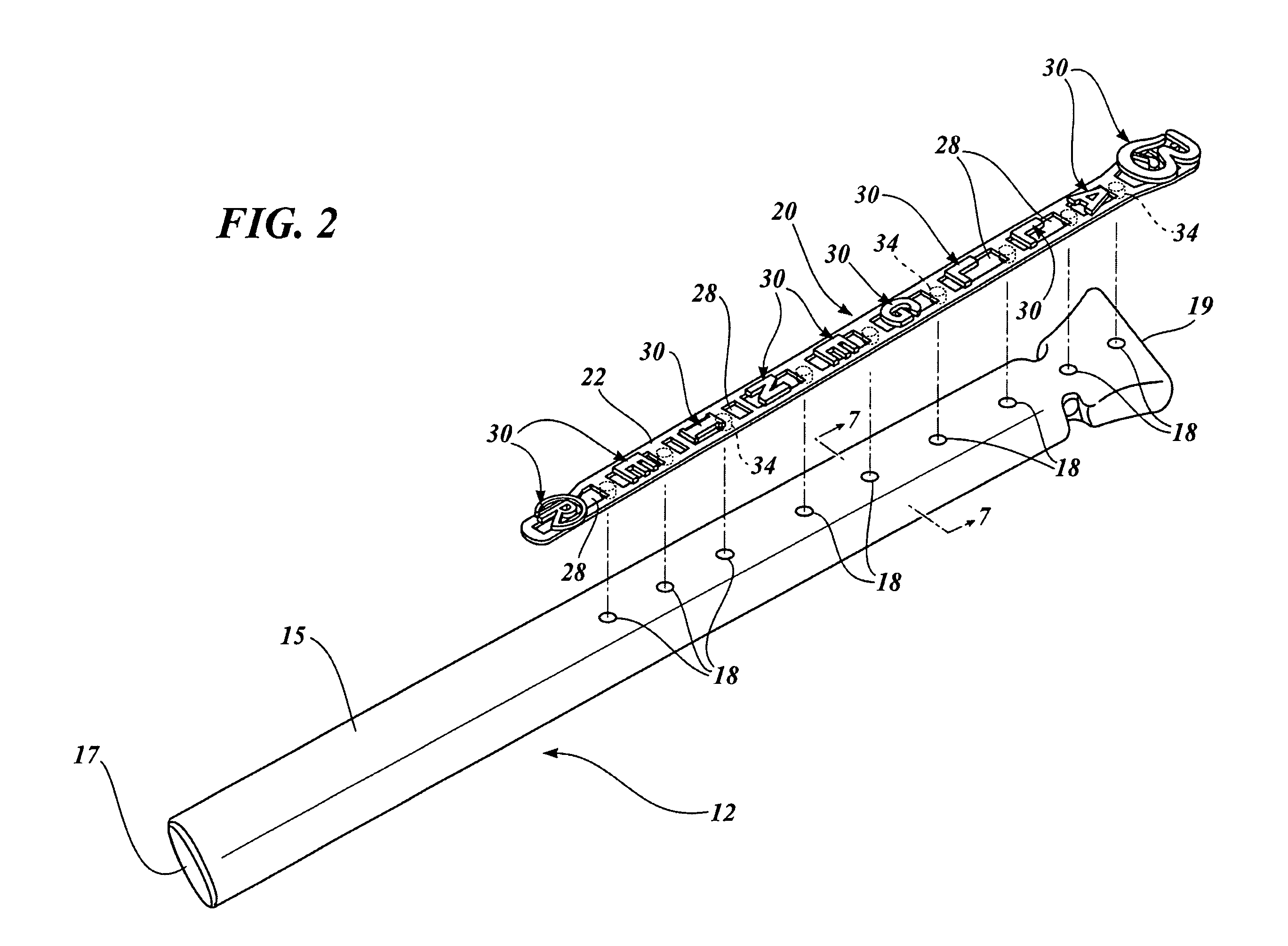
[0039]FIG. 1 illustrates a completed golf club grip 10 constructed according to the invention. The golf club grip 10 is comprised of a hollow, inner, tubular socket 12 which is best illustrated in FIGS. 2 and 7. The hollow, inner socket 12 has an inner surface 13 and an outer surface 15. The socket 12 has an open end 17 for receiving a handle of an implement, such as the handle of a golf club shaft, and an opposite end 19. The tubular socket 12 has a wall structure with a plurality of locating apertures 18 defined therein. The locating apertures are preferably linearly aligned with each other along a line parallel to the axis of the grip.

[0040]The golf club grip 10 also includes a placard 20 which is formed with a mounting base 22 having an inner surface 24 and an outer surface 26. Flow openings 28 are defined through the structure of the placard base 22.

[0041]The placard 20 includes at least one, and preferably a plurality of raised displays 30 in the form of raised letters or othe...


PUM


Abstract

An improved construction for a grip, such as a golf club grip, employs interchangeable placards that may be utilized upon identical sockets formed in a first mold. The placards are constructed with at least one, and preferably a plurality, of raised displays, such as display symbols in the form of letters, numbers, geometric designs, and other display figures. Any number of different placards may alternatively be mounted upon a socket to produce a grip according to the present invention. The socket and placard are positioned by means of positioning pegs on the underside of the mounting base of the placard. The positioning pegs are inserted into corresponding locator openings in the wall of the socket. The socket, together with the placard mounted thereon, is positioned in a second mold having a mold cavity larger than the mold cavity of the first mold in which the socket is produced. The second mold is configured so that the display face or faces of the displays projecting out from the upper surface of the placard reside in contact with the inner molding surface of the second mold. A second charge of molten material is injected into the second mold, thereby forming a jacket that encapsulates the socket, covers the mounting base of the placard, and surrounds all of the raised displays on the placard. However, the display faces of the raised displays of the placard remain exposed.

Description

BACKGROUND OF THE INVENTION[0001]1. Field of the Invention[0002]The present invention relates to an improved grip for an implement having a handle, and the method of manufacture of such a grip. The invention has particular utility in the manufacture of golf club grips.[0003]2. Description of the Prior Art[0004]Golf club grips and grips for other implements have a wide variety of different constructions and have been fabricated in different ways over the years. The shaft of a golf club is an elongated, narrow, generally cylindrical structure which may be formed of solid wood, a solid metal rod, or hollow metal tubing, closed at the end remote from the golf club head. The extremity of the shaft of the golf club remote from the head serves as a handle, and is usually no more than about five-eighths of an inch in diameter. The golf club shaft is typically quite smooth, so that a grip of some type on the handle end is essential to allow a golfer to control the swing of the club.[0005]Con...

Claims


Application Information

Patent Timeline
IPC IPC(8): A63B53/14
CPCA63B53/14A63B60/14A63B60/00
Inventor DOWNEY, PHILIP L.
Owner DOWNEY PHILIP L
Why Eureka
Try Eureka