
Wien filter with reduced chromatic aberration

a technology of chromatic aberration and wien filter, applied in the field of wien filters, can solve the problem that the chromatic aberration in the conventional wien filter is caused by the conventional filter

Active Publication Date: 2007-01-16
KLA TENCOR TECH CORP
View PDF18 Cites 28 Cited by
  • Summary
  • Abstract
  • Description
  • Claims
  • Application Information

AI Technical Summary

Benefits of technology

[0019]Another embodiment disclosed relates to a Wien filter type device wherein the magnetic force is approximately twice in strength compared to the electrostatic force. The device may be configured to deflect an incident beam of charged particles towards a target substrate and to deflect a scattered beam from the substrate to a detector. Advantageously, the device may be configured to reduce or eliminate the chromatic aberration caused by the device.

Problems solved by technology

As pointed out in the present disclosure, one disadvantageous aspect of a conventional Wien filter is the chromatic aberration that is induced.

Method used


Image

  • Wien filter with reduced chromatic aberration
  • Wien filter with reduced chromatic aberration
  • Wien filter with reduced chromatic aberration

Examples


Embodiment Construction

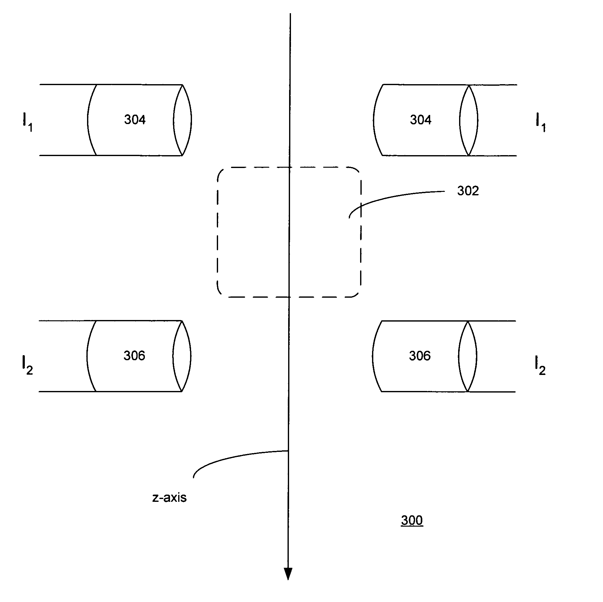
[0021]FIG. 3A is a schematic diagram depicting a first configuration 300 for a Wien filter in accordance with an embodiment of the invention. In this embodiment, the first-order chromatic aberration may be reduced or eliminated by offsetting the effective position of the magnetic field with respect to the electrostatic field.

[0022]In FIG. 3A, the z-axis is shown as going downwards within the page. The trajectory of the charged particles entering the Wien filter is along the z-axis. The Wien filter configuration 300 is such that the electrostatic field is perpendicular to the plane of the page in the approximate area 302 indicated near the center of FIG. 3A.

[0023]Unlike the conventional Wien filter, the Wien filter configuration 300 of FIG. 3A includes two pairs of magnetic deflection coils 304 and 306, each pair of coils being offset relative to the average z-position of the electrostatic field 302. One pair of coils 304 is offset in a negative z-direction relative to the average po...


PUM


Abstract

One embodiment disclosed relates to a Wien filter for a charged-particle beam apparatus. The charged-particle beam is transmitted through the Wien filter in a first direction. A magnetic field generation mechanism is configured to generate a magnetic field in a second direction which is perpendicular to the first direction, and an electrostatic field generation mechanism is configured to generate an electrostatic field in a third direction which is perpendicular to the first and second directions. The field generation mechanisms are further configured so as to have an offset between the positions of the magnetic and electrostatic fields along the first direction. Another embodiment disclosed relates to a Wien filter type device wherein the magnetic force is approximately twice in strength compared to the electrostatic force. Other embodiments are also disclosed.

Description

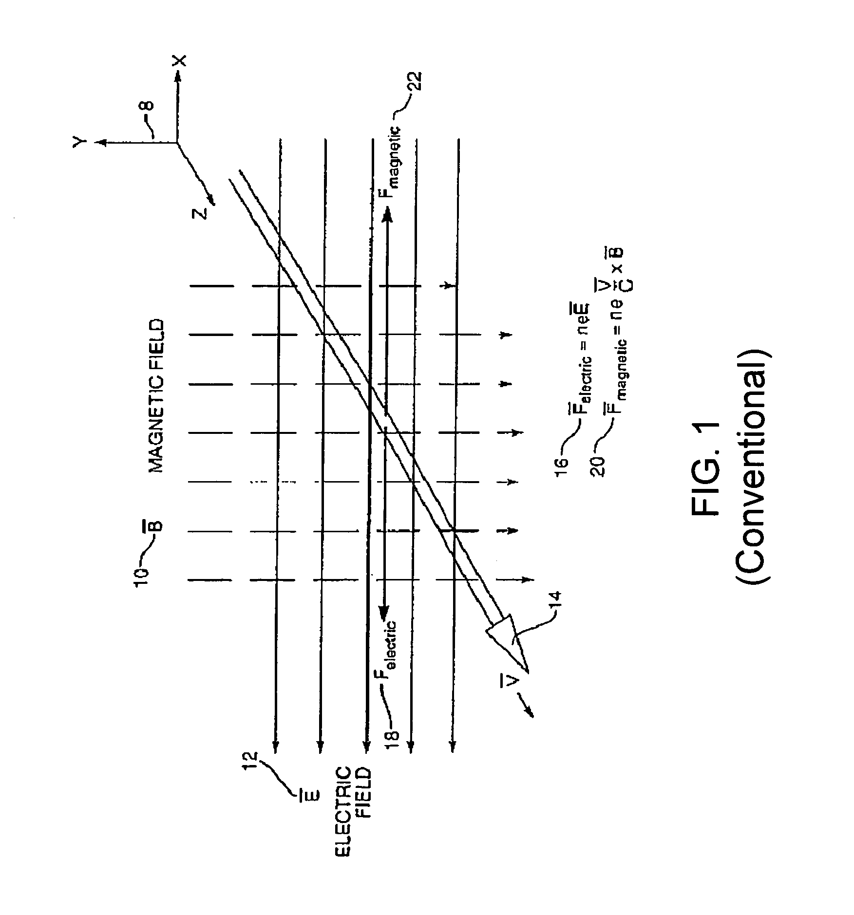
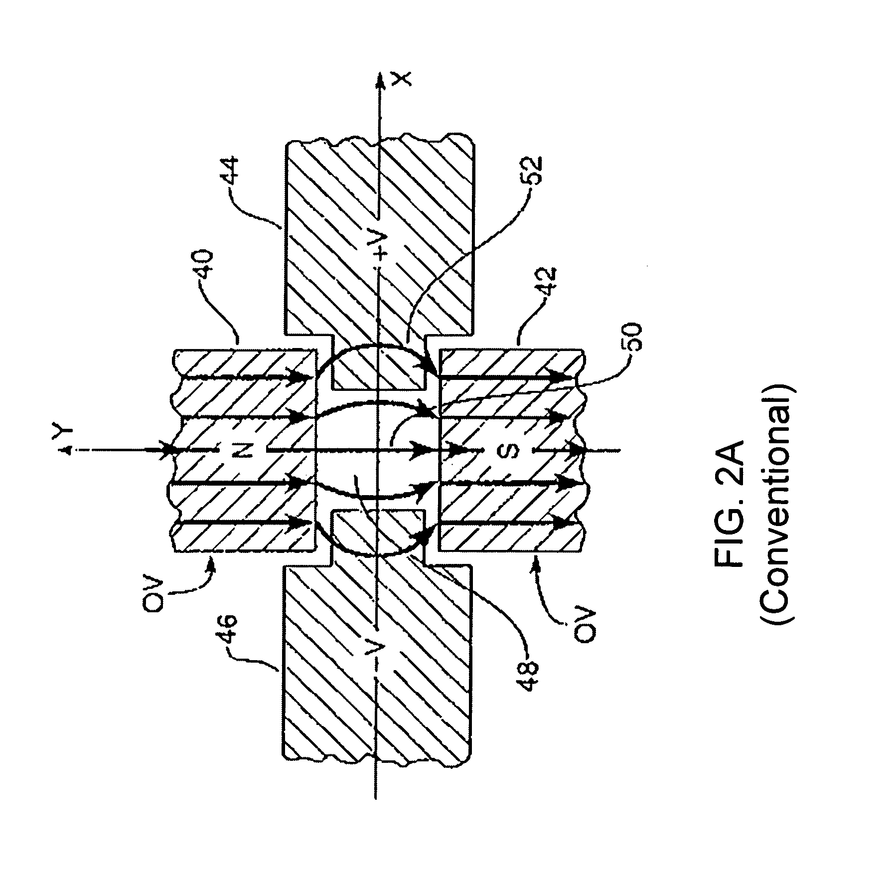
BACKGROUND OF THE INVENTION[0001]1. Field of the Invention[0002]The present invention relates generally to Wien filters, such as those used in charged-particle beam systems and for other purposes.[0003]2. Description of the Background Art[0004]FIG. 1 illustrates the operating principle of the Wien filter. This type of velocity (momentum) filter uses crossed electric and magnetic fields to exert opposing forces on charged particles passing through the filter. An X-Y-Z orthogonal coordinate system 8 is shown.[0005]A substantially homogeneous magnetic field 10 of magnitude B is directed parallel to the Y-axis in the negative direction. A substantially homogeneous electric field 12 of magnitude E is directed parallel to the X-axis, also in the negative direction. A beam of charged particles 14 is directed initially (before encountering the fields 10 and 12) parallel to the Z-axis in the positive direction, and through the electric and magnetic fields. The fields 10 and 12 are positioned...

Claims


Application Information

Patent Timeline
IPC IPC(8): H01J1/50
CPCH01J37/05H01J2237/057
Inventor TOTH, GABOR D.MASNAGHETTI, DOUGLAS K.KEISTER, JEFFREYMUNRO, ERIC
Owner KLA TENCOR TECH CORP
Learn More