Brushless motor drive device

a brushless, multi-phase technology, applied in the direction of motor/generator/converter stopper, electronic commutator, dynamo-electric converter control, etc., can solve the problems of motor's stability of rotation, and achieve the effect of effectively preventing sinusoidal drive signals

Inactive Publication Date: 2007-01-16
GLOBAL MIXED MODE TECH
View PDF10 Cites 47 Cited by
  • Summary
  • Abstract
  • Description
  • Claims
  • Application Information

AI Technical Summary

Benefits of technology

[0010]In view of the above-mentioned problems, an object of the present invention is to provide a brushless motor drive device capable of effectively preventing the sinusoidal drive signals from the influence caused by the variations of the amplitudes of the Hall sensing signals.

Problems solved by technology

Since the amplitudes of the sinusoidal drive signals SU, SV, and SW have effects on determining the duty ratios of the pulse signals PU, PV, and PW generated from the PWM comparing circuit 13, the conventional signal synthesizing circuit 12 renders the operation of the motor M subjected to the variations of the Hall sensing signals HU, HV, and HW, which is a disadvantage with respect to motor's stability of rotation.

Method used


Image

  • Brushless motor drive device
  • Brushless motor drive device
  • Brushless motor drive device

Examples


Embodiment Construction

[0022]The preferred embodiments according to the present invention will be described in detail with reference to the drawings.

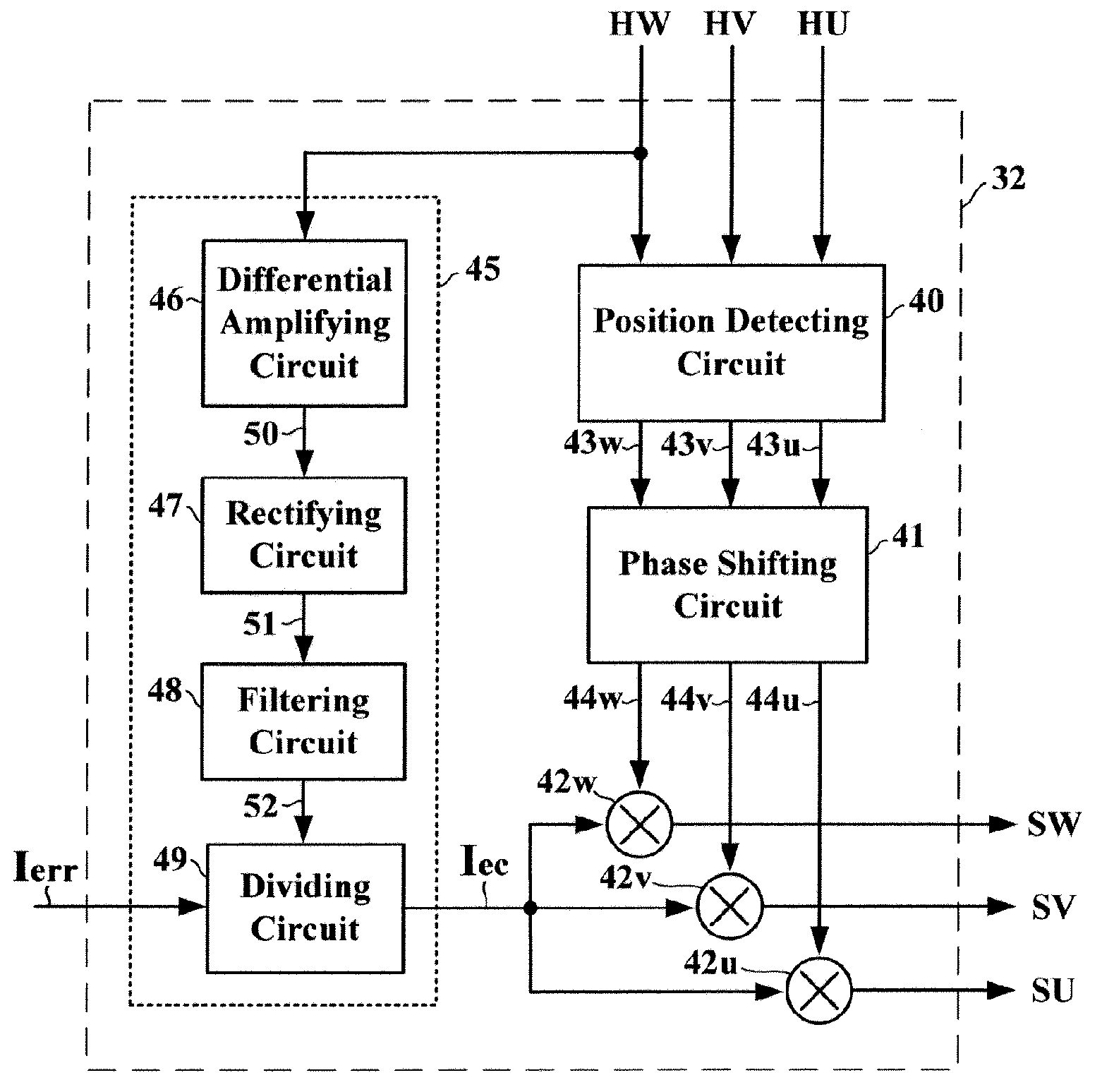
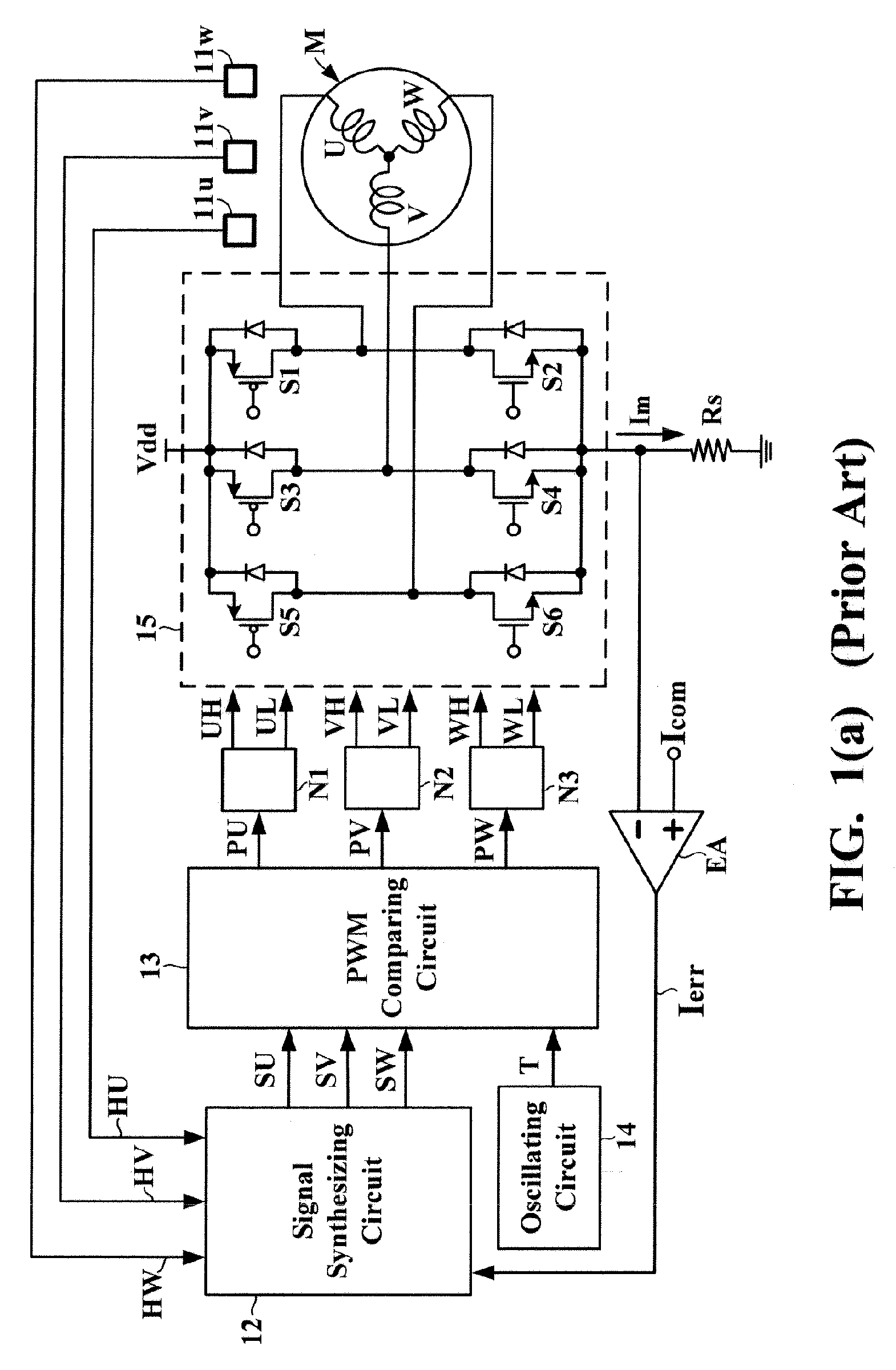
[0023]FIG. 2 is a circuit block diagram showing a signal synthesizing circuit 32 according to the present invention. The signal synthesizing circuit 32 is applied in the brushless motor drive device shown in FIG. 1(a), for replacing the conventional signal synthesizing circuit 12. As already described with reference to FIG. 1(a), the motor M is a three-phase DC brushless motor having three phase coils U, V, and W. The three Hall sensing elements 11u, 11v, and 11w, which together make up a sensing circuit, are arranged around the motor M for generating three Hall sensing signals HU, HV, and HW in response to variations in the magnetic field of the motor M. Based on the Hall sensing signals HU, HV, and HW, the signal synthesizing circuit 32 according to the present invention generates three sinusoidal drive signals SU, SV, and SW. Subsequently, the sinusoidal d...


PUM


Abstract

A brushless motor drive device has a signal synthesizing circuit for converting a plurality of sensing signals into a plurality of drive signals so as to determine an amplitude of each of the drive signals in accordance with a current error signal. The sensing signals are generated by a sensing circuit in response to variations in a magnetic field of a brushless multi-phase motor. The current error signal is representative of a difference between a current command signal and a motor drive current. The signal synthesizing circuit is characterized by including a calibrating circuit for adjusting the current error signal in accordance with an amplitude of any of the sensing signals. The calibrating circuit includes a differential amplifying circuit, a rectifying circuit, a filtering circuit, and a dividing circuit.

Description

BACKGROUND OF THE INVENTION[0001]1. Field of the Invention[0002]The present invention relates to a motor drive device and, more particularly, to a motor drive device for a brushless multi-phase DC motor.[0003]2. Description of the Related Art[0004]FIG. 1(a) is a circuit block diagram showing a conventional brushless motor drive device. Referring to FIG. 1(a), a motor M is a three-phase DC brushless motor having three phase coils U, V, and W. Three Hall sensing elements 11u, 11v, and 11w are arranged around the motor M for generating three Hall sensing signals HU, HV, and HW in response to variations in the magnetic field of the motor M. Based on the Hall sensing signals HU, HV, and HW, a signal synthesizing circuit 12 generates three sinusoidal drive signals SU, SV, and SW. Subsequently, the sinusoidal drive signals SU, SV, and SW are input to a pulse width modulation (PWM) comparing circuit 13 for being individually compared with respect to a high-frequency triangular reference sig...

Claims


Application Information

Patent Timeline
Patent Type & Authority Patents(United States)
IPC IPC(8): H02P7/06
CPCH02P6/142H02P6/002H02P6/15H02P6/28
Inventor CHEN, CHI-YANG
Owner GLOBAL MIXED MODE TECH
Why Eureka
Try Eureka