
Flicker correction apparatus and flicker correction method, and recording medium storing flicker correction program

a technology of flicker correction and flicker correction, which is applied in the field of flicker correction apparatus and flicker correction method, and the storage of flicker correction programs on the recording medium, can solve the problems of high power consumption of ccd type imaging devices, increased number of parts, and difficulty in building a small-sized portable electronic camera system employing such a ccd type imaging device, so as to prevent flicker phenomenon and reduce image quality

Active Publication Date: 2007-01-16
SHARP KK
View PDF12 Cites 27 Cited by
  • Summary
  • Abstract
  • Description
  • Claims
  • Application Information

AI Technical Summary

Benefits of technology

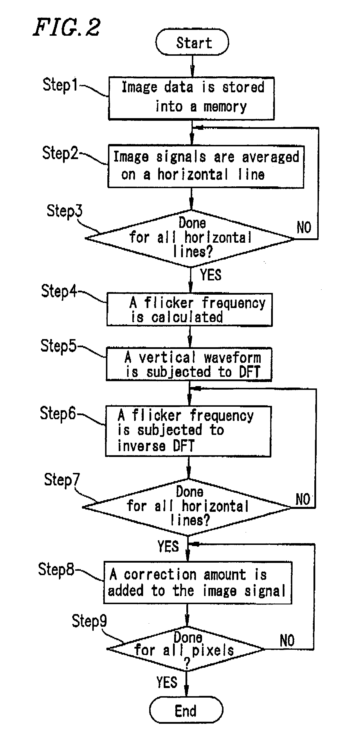
[0035]Therefore, the flicker determination section can determine the presence or absence of a flicker phenomenon, thereby making it possible not to perform flicker correction for an image obtained under the illumination which does not cause a flicker phenomenon, such as sunlight or the like. Moreover, flicker data is extracted using the average of image signals calculated for each line or each group of lines in the horizontal or vertical direction, and a flicker frequency calculated using an AC power source frequency and the frame or field frequency of an image device. A flicker correction amount is calculated from the flicker data. Therefore, data corresponding to frames or fields having the same bright or dark stripe is not required as is different from conventional flicker correction apparatuses. Therefore, flicker correction can be rapidly performed irrespective of the frame or field frequency of an imaging device.
[0055]Thus, the invention described herein makes possible the advantages of providing a flicker correction apparatus, a flicker correction method, and a recording medium storing a flicker correction program capable of performing rapid flicker correction irrespective of the frame or field frequency of an imaging device even when illumination and an AC power source frequency are changed.

Problems solved by technology

The CCD type imaging device requires high power consumption and increases the number of parts.
Therefore, it is not easy to construct a small-sized portable electronic camera system employing such a CCD type imaging device.
In this case, an image is adversely affected by flicker correction.
Therefore, it takes a long time to correct a flicker depending on the frame or field frequency of an imaging device.

Method used


Image

  • Flicker correction apparatus and flicker correction method, and recording medium storing flicker correction program
  • Flicker correction apparatus and flicker correction method, and recording medium storing flicker correction program
  • Flicker correction apparatus and flicker correction method, and recording medium storing flicker correction program

Examples


example 1

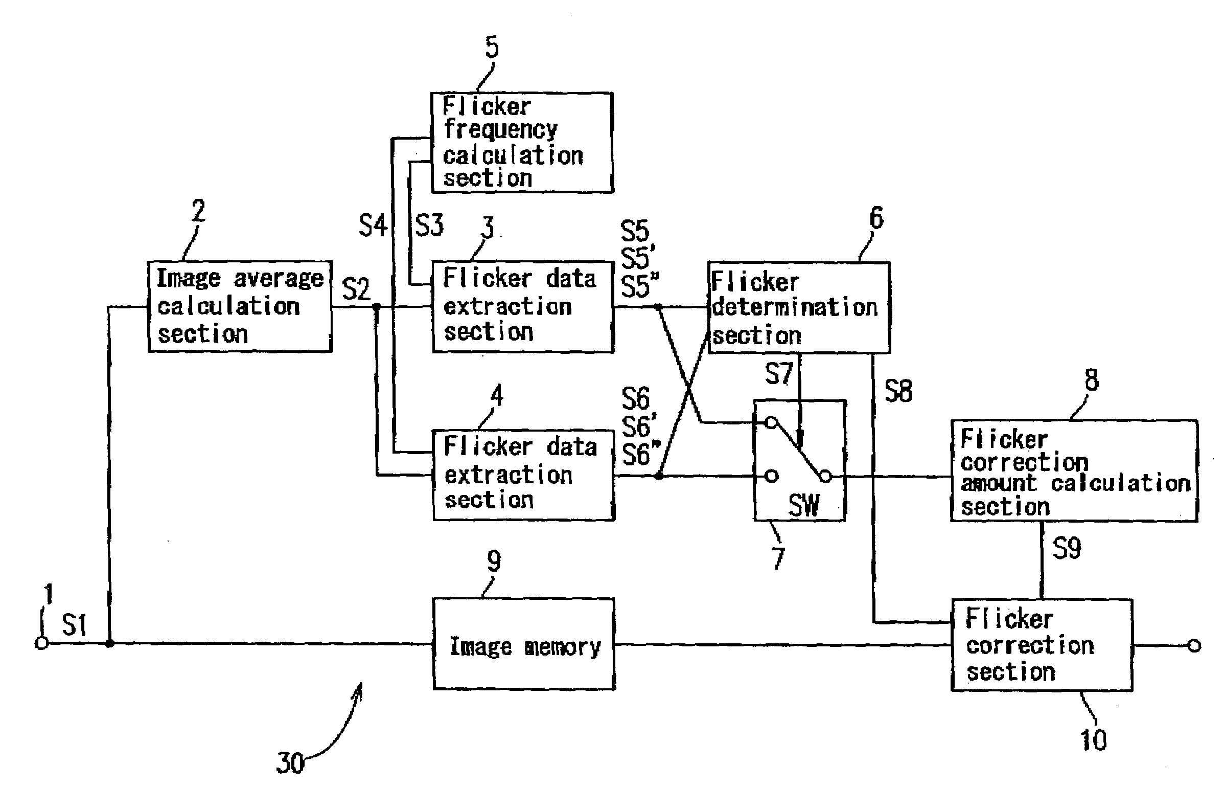
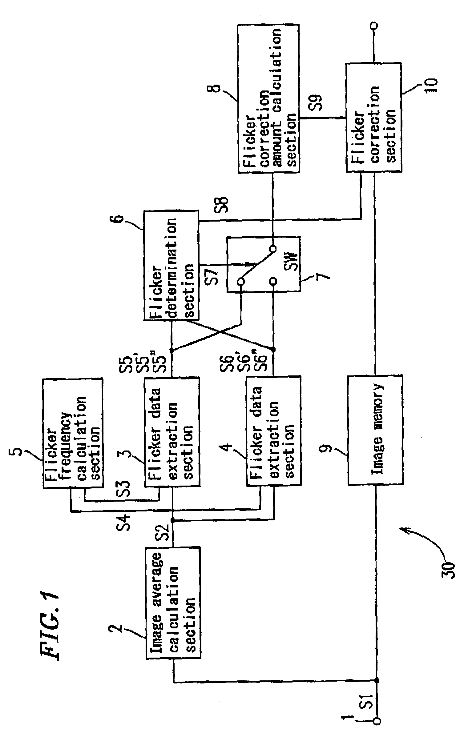
[0067]FIG. 1 is a schematic block diagram showing a configuration of a flicker correction apparatus 30 according to Example 1 of the present invention.

[0068]This flicker correction apparatus 30 has an input terminal 1 through which an image signal S1 is input. The image signal S1 is obtained by imaging an object using a camera comprising an imaging device, such as an electronic camera, a scanner, or the like. For example, when an object is imaged by a camera comprising an X-Y address scanning type solid-state imaging device (e.g., a CMOS type image sensor, etc.) under the illumination of a fluorescent lamp which blinks in synchronization with the frequency of an AC power source, the image signal Si containing a flicker component is input through the input terminal 1.

[0069]The image signal S1 input through the input terminal 1 is supplied to an image memory 9, and one frame or one field of the image signal is stored as image data into the image memory 9. The image signal S1 is also s...

example 2

[0099]FIG. 4 is a schematic block diagram showing a configuration of a flicker correction apparatus 40 according to Example 2 of the present invention.

[0100]This flicker correction apparatus 40 is not provided with an image memory 9 as in the flicker correction apparatus 30 of Example 1 (FIG. 1). For example, a flicker correction amount is calculated based on a frame or field of the image signal previously input through an input terminal 1, such as a first previous frame or field, and such a flicker correction amount is used to correct a frame or field of the image signal currently input through the input terminal 1. In this case, there is a difference in the phase of a flicker component between the previous frame (or field) and the current frame (or field), and therefore, flicker correction has to be performed by taking the phase difference into consideration. In order to calculate the phase difference, the flicker correction apparatus 40 of Example 2 is provided with a phase diffe...

example 3

[0108]FIG. 5 is a schematic block diagram showing a configuration of a flicker correction apparatus 50 according to Example 3 of the present invention.

[0109]In this flicker correction apparatus 50, an image signal S1 input through an input terminal 1 is supplied to an image average calculation section 2 and a flicker correction section 10 as in the flicker correction apparatus 40 of Example 2 (FIG. 4). Further, the image signal S1 is supplied to a flicker correction amount calculation section 8.

[0110]A horizontal, bright-and-dark striped pattern due to a flicker phenomenon is less conspicuous in a dark portion of an object than in a bright portion since a contrast is reduced in a dark portion. Therefore, when a bright pixel and a dark pixel are present on the same horizontal line in one frame or field of image, if the same flicker correction amount is added to the bright pixel and the dark pixel, an image may be degraded.

[0111]In order to avoid such image degradation, in the flicker...


PUM


Abstract

A flicker correction apparatus for correcting a flicker component of an image signal obtained by imaging an object using an imaging device is provided. The apparatus comprises an image average calculation section for calculating an average of the image signal, a flicker frequency calculation section for calculating a flicker frequency, a flicker data extraction section for extracting flicker data using the average of the image signal and the flicker frequency, a flicker determination section for determining the presence or absence of a flicker phenomenon using the flicker data, a flicker correction amount calculation section for calculating a flicker correction amount using the flicker data, and a flicker correction section for removing the flicker component of the image data using the flicker correction amount.

Description

BACKGROUND OF THE INVENTION[0001]1. Field of the Invention[0002]The present invention relates to a flicker correction apparatus, a flicker correction method, and a recording medium storing a flicker correction program for correcting a flicker component of an image signal obtained by imaging an object using an imaging device. More particularly, the present invention relates to a flicker correction apparatus, a flicker correction method, and a recording medium storing a flicker correction program capable of preventing the occurrence of a flicker phenomenon. The flicker phenomenon is such that when an object is imaged using an X-Y address scanning type solid-state imaging device under the illumination of a fluorescent lamp flickering in synchronization with the frequency of an alternating current (AC) power source, a striped pattern of dark color portions and light color portions extending in the horizontal direction appear in the image.[0003]2. Description of the Related Art[0004]Elec...

Claims


Application Information

Patent Timeline
Patent Type & Authority Patents(United States)
IPC IPC(8): H04N9/73H04N5/228H01L27/146H04N23/40H04N25/00
CPCH04N5/235H04N5/2357Y10S348/91H04N23/70H04N23/745H04N5/21
Inventor YOSHIDA, TAKUJIKIMURA, KATSUJIKUBO, NOBORUOKUHATA, HIROYUKIKAYA, TOSHIYUKIHAMANAKA, SHINSUKEONO, EIJISHIRAKAWA, ISAO
Owner SHARP KK
Learn More