Modular chassis divided along a midplane and cooling system therefor

a module chassis and cooling system technology, applied in the direction of electrical apparatus casings/cabinets/drawers, electrical apparatus construction details, instruments, etc., can solve the problems of long assembly time, inconvenient rear access, time-consuming and laborious connection of components, etc., and achieve the effect of reducing cost, manufacturing and servi

Active Publication Date: 2007-01-16
MCDATA SERVICES CORP +1
View PDF18 Cites 47 Cited by
  • Summary
  • Abstract
  • Description
  • Claims
  • Application Information

AI Technical Summary

Benefits of technology

[0009]The chassis design of the present invention addresses these and other concerns. The chassis of the present invention is divided along a midplane into front and rear sections, allowing convenient access to the midplane for quick, and therefore lower cost, manufacture and service. Captive hardware accessible from the rear of the chassis further facilitates convenient access to the interior of the chassis. Tabs and mating recesses along the junction between the front and rear chassis sections allow for safe and simple joining and disjoining of the front and rear sections. Further, components attached to the miplane can all be removed or installed without requiring disassembly or opening of the chassis.
[0010]A compact, modular configuration and layout to the electrical circuitry and supporting components further aids in making assembly and service of the system convenient. In particular, organization and layout of the components to allow direct connections via high density connectors of all components to the midplane, without individual wires, reduces manufacturing time and reduces errors in assembly and service. In addition, the quick connections facilitate quick and reliable servicing of the chassis for maintenance and upgrades.

Problems solved by technology

With a midplane design, however, this rear access is inconvenient because to access the midplane, all of the components to the rear of the midplane must be removed to access the midplane.
Another issue for chassis design, particularly with a midplane, is providing for convenient connections between components.
More specifically, when components are assembled in the chassis during manufacture, it is time-consuming and labor intensive to connect components through wires that must be manually and individually secured.
Assembly time is lengthened, and therefore manufacturing cost is increased, since the manual connection of individual wires is slow and allows for errors which, when discovered, require diagnosis of the problem, disassembly, and reassembly, allowing for further connection error.
Neatly containing wires and wire harnesses so that they are not in the way of other components is also a problem.
Further, maintenance is slow and prone to connection error when individual wirings must be made.
Expansion and upgradeability are other issues of concern for chassis for such systems.
Chassis design must also provide for efficient, effective cooling of the components inside because they generate heat during operation and will not operate properly or may be damaged if overheated.

Method used


Image

  • Modular chassis divided along a midplane and cooling system therefor
  • Modular chassis divided along a midplane and cooling system therefor
  • Modular chassis divided along a midplane and cooling system therefor

Examples


Embodiment Construction

)

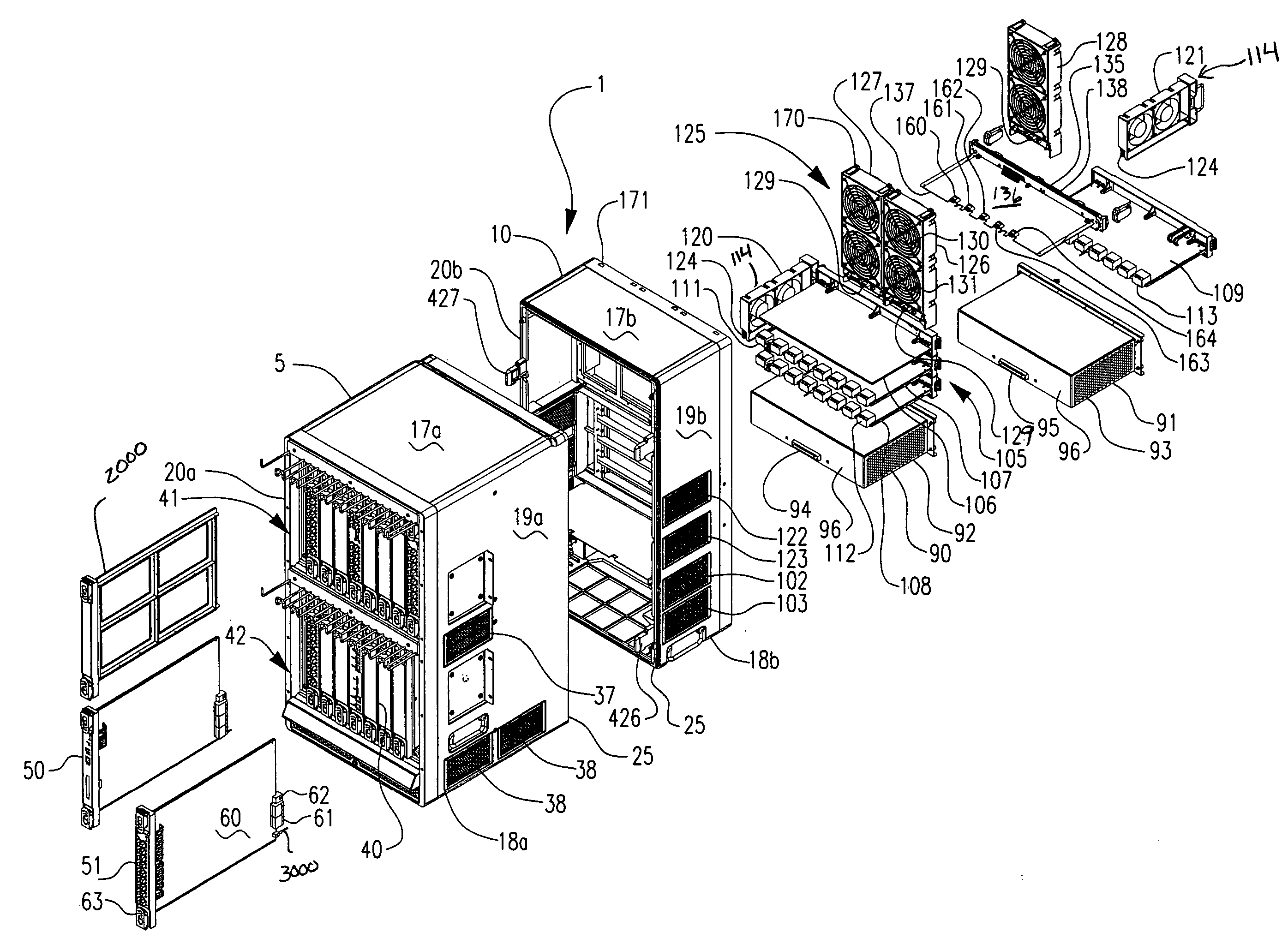
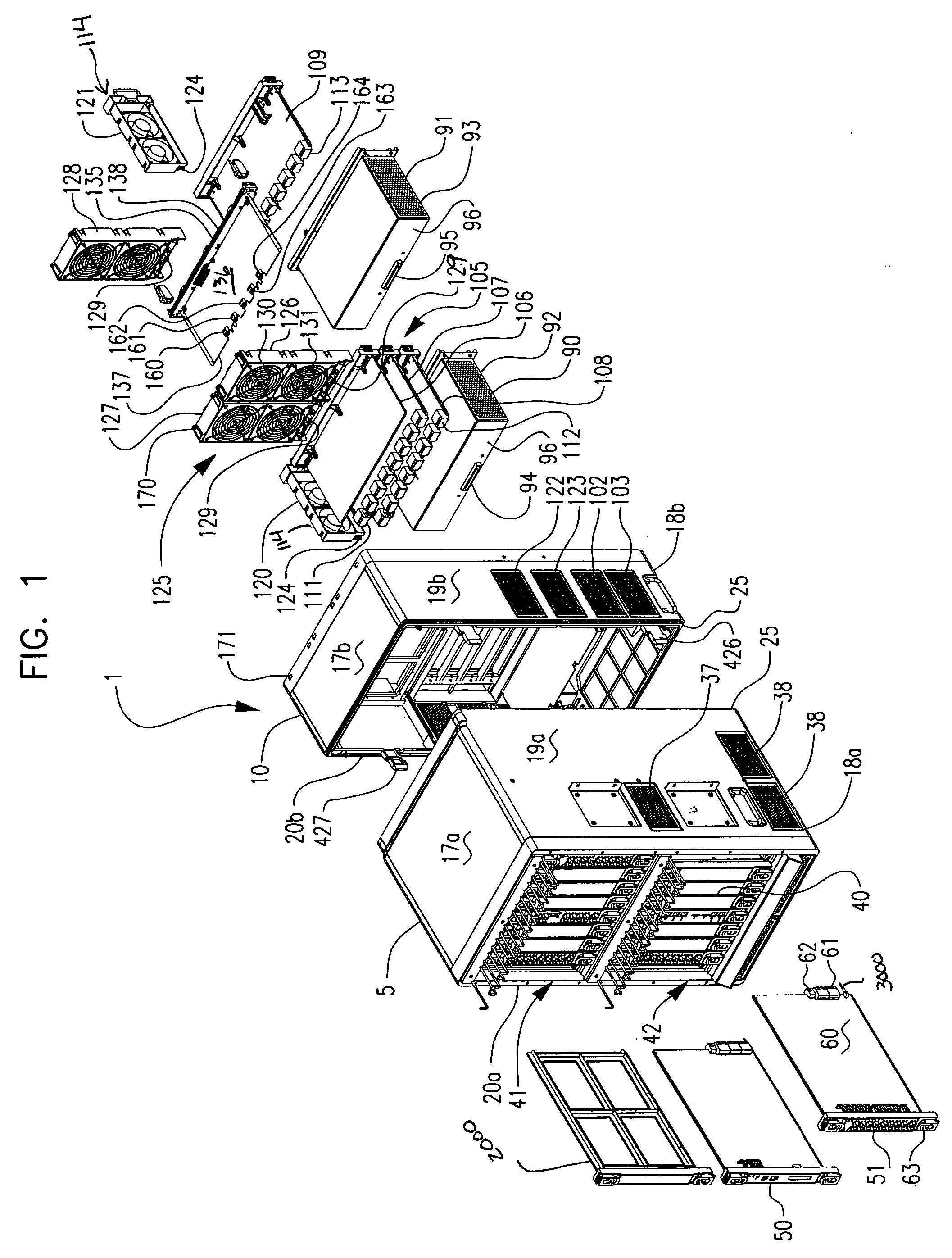
[0031]FIG. 1 shows an exploded view of a preferred embodiment of a chassis 1 for housing electrical circuitry, such as high speed switching or routing systems. The chassis 1 has generally two sections: a front section 5 and a rear section 10. It should be understood that the terms “front” and “rear” as used throughout reflect the orientation pictured in FIG. 1, and are used consistently through this description and the claims. They do not, however, necessarily have operational meaning and are not intended to be limiting; in other words, they might be reversed throughout without altering the description. The same is true for the terms “top”, “bottom”, “side”, “right”, “left”, “vertical” and “horizontal”. The front section 5 houses or supports an array of printed circuit board assemblies as will be described below. The rear section 10 houses or supports fan assemblies, printed circuit board assemblies and power supplies, as will be described below.

[0032]The chassis 1 has a generally ...


PUM


Abstract

A chassis divides vertically, with front and rear sections of the chassis joined immediately adjacent a midplane printed circuit board that supports interconnectivity of electronic circuits. Wiring within the chassis is eliminated through directed connections of all components to the midplane. Minimal hardware is required for securing the front and rear sections together, and therefore accessing the midplane for assembly and service is convenient. All components except the midplane are installed and removed from either the front or rear of the chassis without opening or disassembling the chassis. The chassis layout and features facilitate effective cooling of the components in the chassis.

Description

FIELD OF THE INVENTION[0001]The present invention relates generally to a chassis for housing electrical circuitry and more particularly to a modular chassis with a midplane located at the juncture of front and rear chassis sections, with electrical circuitry components connecting to the midplane. The invention further relates to a cooling system for electrical circuitry within a chassis.BACKGROUND OF THE INVENTION[0002]High speed switches, routers and the like are assemblies of electrical circuitry, including printed circuit boards and supporting components such as power supplies and fans to cool the system. Such systems are typically housed in a chassis that in turn is often mounted in an equipment rack.[0003]The printed circuit boards, include input / output (I / O) boards, processing boards and switching boards. Boards within the switch or router connect to other boards within the chassis, directly or indirectly, to allow data transfer therbetween.[0004]To support the ever-increasing...

Claims


Application Information

Patent Timeline
Patent Type & Authority Patents(United States)
IPC IPC(8): G06F1/16H05K9/00H05K5/00H05K7/14H05K7/20
CPCH05K7/1451H05K7/20572H05K7/1445
Inventor CARULLO, THOMAS J.WILLERS, ARTHUR G.GOODENOUGH, RYAN K.
Owner MCDATA SERVICES CORP
Why Eureka
Try Eureka