Blast-resistant cargo container

a cargo container, blast-resistant technology, applied in the field of cargo containers, can solve the problems of varying or controlling the bending stiffness of the structure, and achieve the effect of minimizing the bending stress

Inactive Publication Date: 2007-01-23
IND TECH RES INST
View PDF17 Cites 12 Cited by
  • Summary
  • Abstract
  • Description
  • Claims
  • Application Information

AI Technical Summary

Benefits of technology

[0014]An objective of the present invention is to provide a frameless blast-resistant cargo container with light weight. Under ordinary conditions, the structure has sufficient stiffness for loading goods. When an explosive blast occurs in the cargo container, the structure is sufficiently flexible to deform to spherical-like shape from original box-like shape and can almost fully utilize the membrane strength of the material in the entire structure, whereby the cargo container is capable of withstanding the explosive blast.
[0016]The ductile connecting members are totally different consideration (for example: material, thickness, etc.) with the side panels. During the blast process, they are sufficiently flexible to be stretched and deformed plastically. This causes the stress redistribution gradually such that the bending stress can be minimized near the edges of a cargo container. Such connecting members are introduced in present invention to connect adjacent side panels and can achieve the objective of present invention.
[0017]Our connecting members and side panels construction, which is separable in geometry and material, can provide a mechanism to select different characteristic side panels including light weight panels such as composite or metal laminated composite plates.

Problems solved by technology

Based on the concept of a frameless design, “how to vary or control the bending stiffness of the structure in the edge nearby” is another key problem.

Method used


Image

  • Blast-resistant cargo container
  • Blast-resistant cargo container
  • Blast-resistant cargo container

Examples


Embodiment Construction

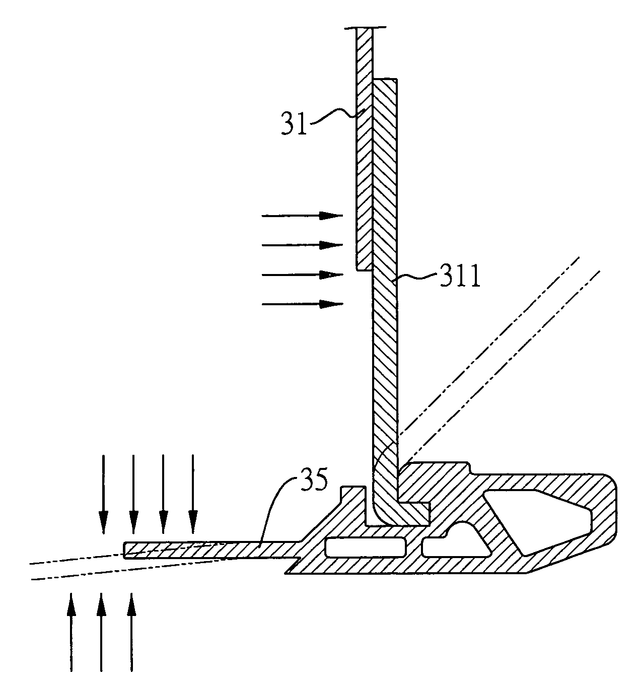
[0027]For the purpose to utilize the membrane strength of a material, especially in the edges nearby, of a blast-resistant container we should use the connecting members which are able to transmit tensile forces between every two adjacent side panels and that it can rotate the member itself like a hinge when a blast occurs. The connecting member can be connected to side panels directly or indirectly. Which means that the both ends of connecting member can be connected to both side panels directly or only one end of connecting member is connected to one side panel, the other one end is not directly connected to the other side panel.

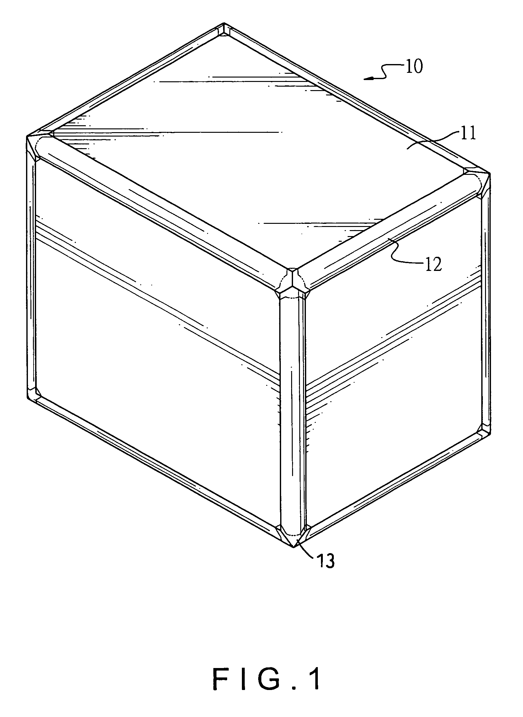
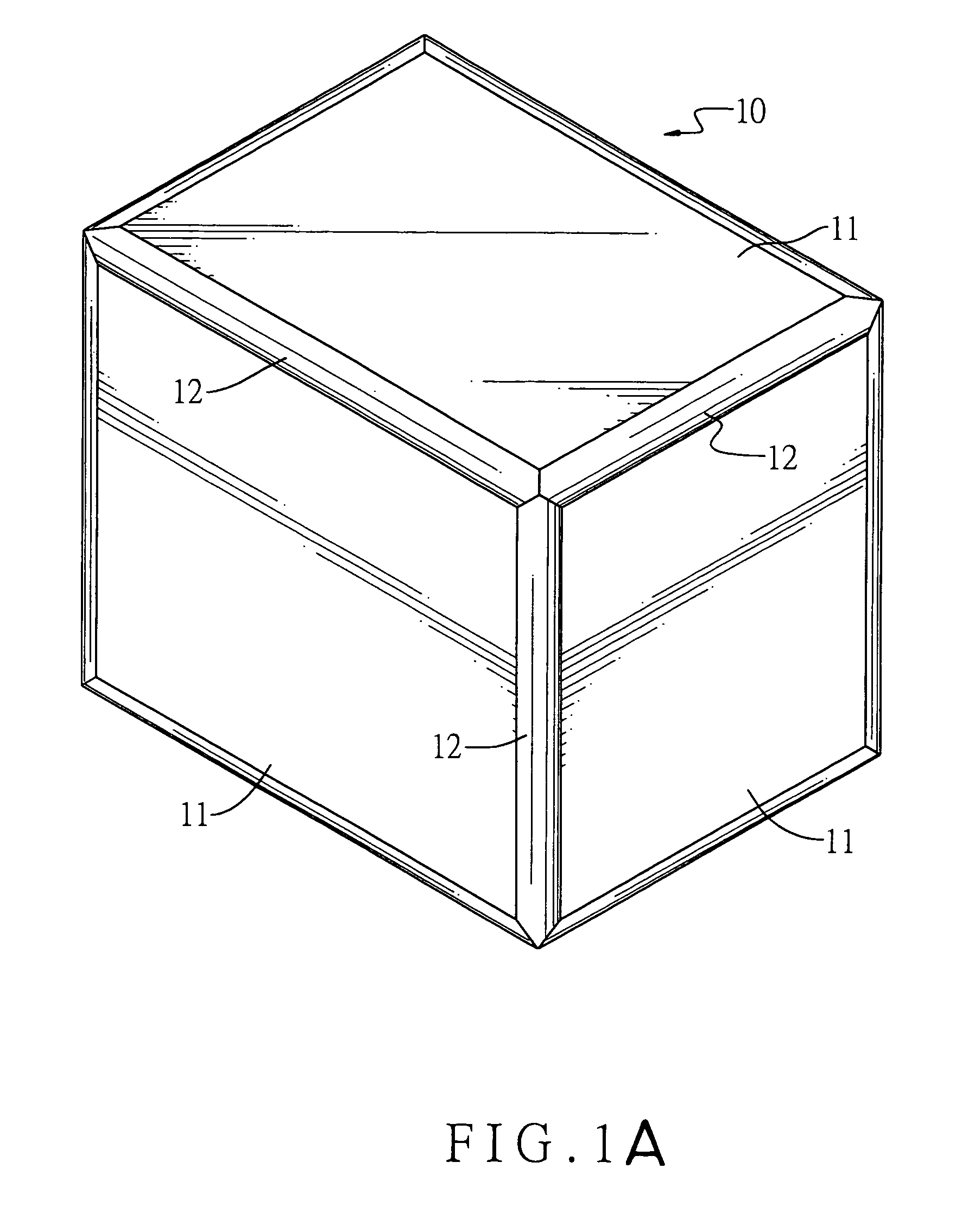
[0028]With reference to FIG. 1, the first preferred embodiment of a blast-resistant cargo container in accordance with the present invention is shown. The cargo container (10) has side panels (11) and plastically stretched connecting members (12) securely connected to adjacent side panels (11), so that a chamber can be formed inside the side panels (11) to...


PUM


Abstract

A blast-resistant cargo container includes side panels and connecting members. The connecting members are mounted between the adjacent side panels to create a frameless structure of the cargo container. Under ordinary conditions, the structure still has sufficient stiffness for loading goods. When an explosive blast occurs in the cargo container, the structure is flexible and utilizes membrane strength in the entire container structure, whereby the cargo container is capable of withstanding the explosive blast. Bottom perimeter bars are able to be mounted around a bottom surface of the cargo container. Grooves are defined in the perimeter bars and L-shaped flanges are formed on one end of the connecting members. Therefore, by receiving the L-shaped flanges into the grooves, the perimeter bars are securely connected with the side panels.

Description

CROSS REFERENCE[0001]The present invention is a continuation-in-part (CIP) of the application Ser. No. 10 / 236,621, filed on Sep. 5, 2002, now abandoned, by the same applicant of the present invention. The content thereof is incorporated for reference hereinafter.BACKGROUND OF THE INVENTIONS[0002]1. Field of the Invention[0003]The present invention relates generally to cargo containers, and more particularly concerns a blast-resistant cargo container that is capable of substantially confining an explosive blast within the cargo container for protecting a carrier such as an airplane.[0004]2. Description of Related Art[0005]Conventional cargo containers are typically designed to have a frame, and panels attached to the frame so as to define a chamber interior for receiving goods. There are many kinds of available cargo containers having different sizes and configurations in order to meet practical needs, wherein an air cargo container is a kind to be used for transporting goods via an ...

Claims


Application Information

Patent Timeline
Patent Type & Authority Patents(United States)
IPC IPC(8): F42B33/06B65D51/00F42B39/14F42D5/04
CPCF42D5/04F42B39/14
Inventor WANG, MING-JONG
Owner IND TECH RES INST
Why Eureka
Try Eureka