
Strip material applicator apparatus

Inactive Publication Date: 2007-01-23
BERRAN INDAL GROUP
View PDF13 Cites 0 Cited by
  • Summary
  • Abstract
  • Description
  • Claims
  • Application Information

AI Technical Summary

Benefits of technology

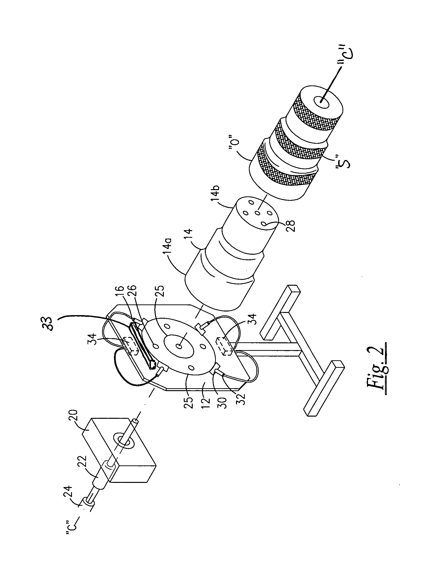
[0016]It is a feature of the present invention to provide an apparatus having a base comprising a plurality of openings formed in the area on which the mandrel rests. The openings operate in conjunction with a plurality of openings formed in the mandrel (at the opposite end) so as to prevent creation of vacuum pressure and lock on the object when placed on the mandrel.
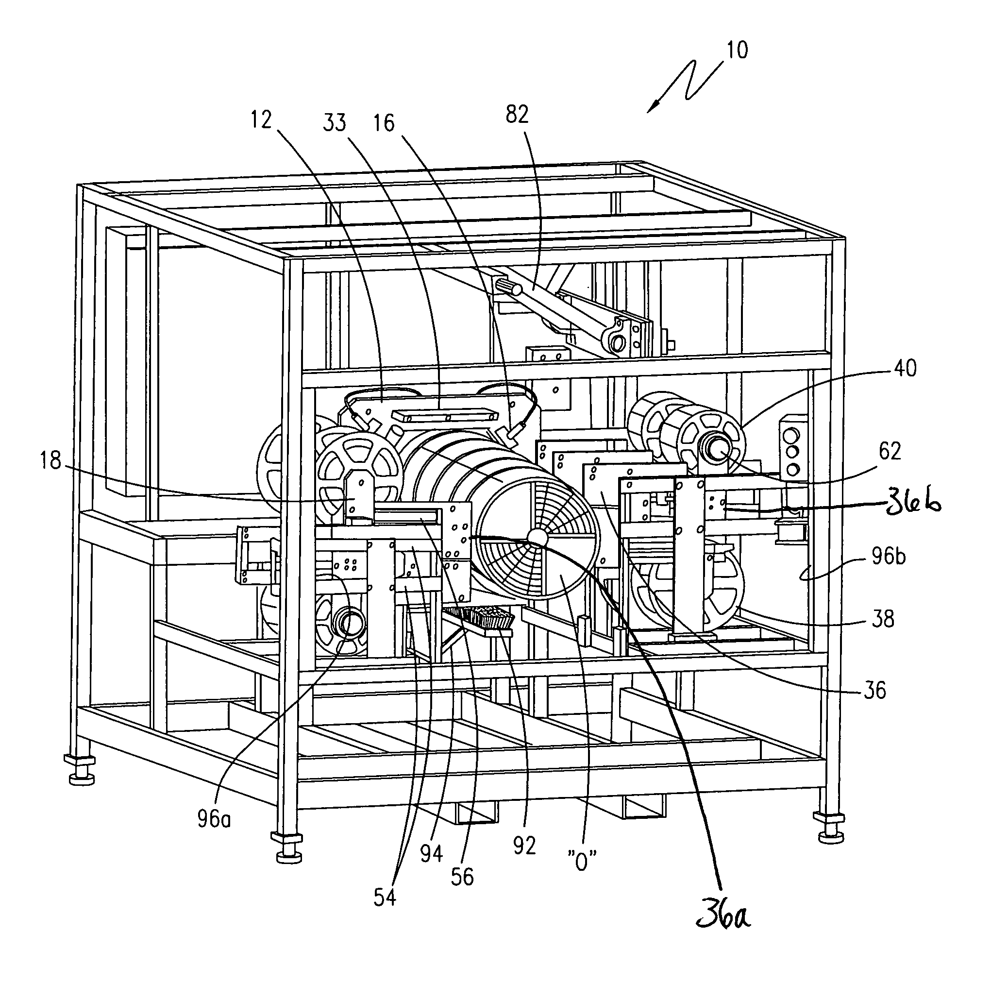
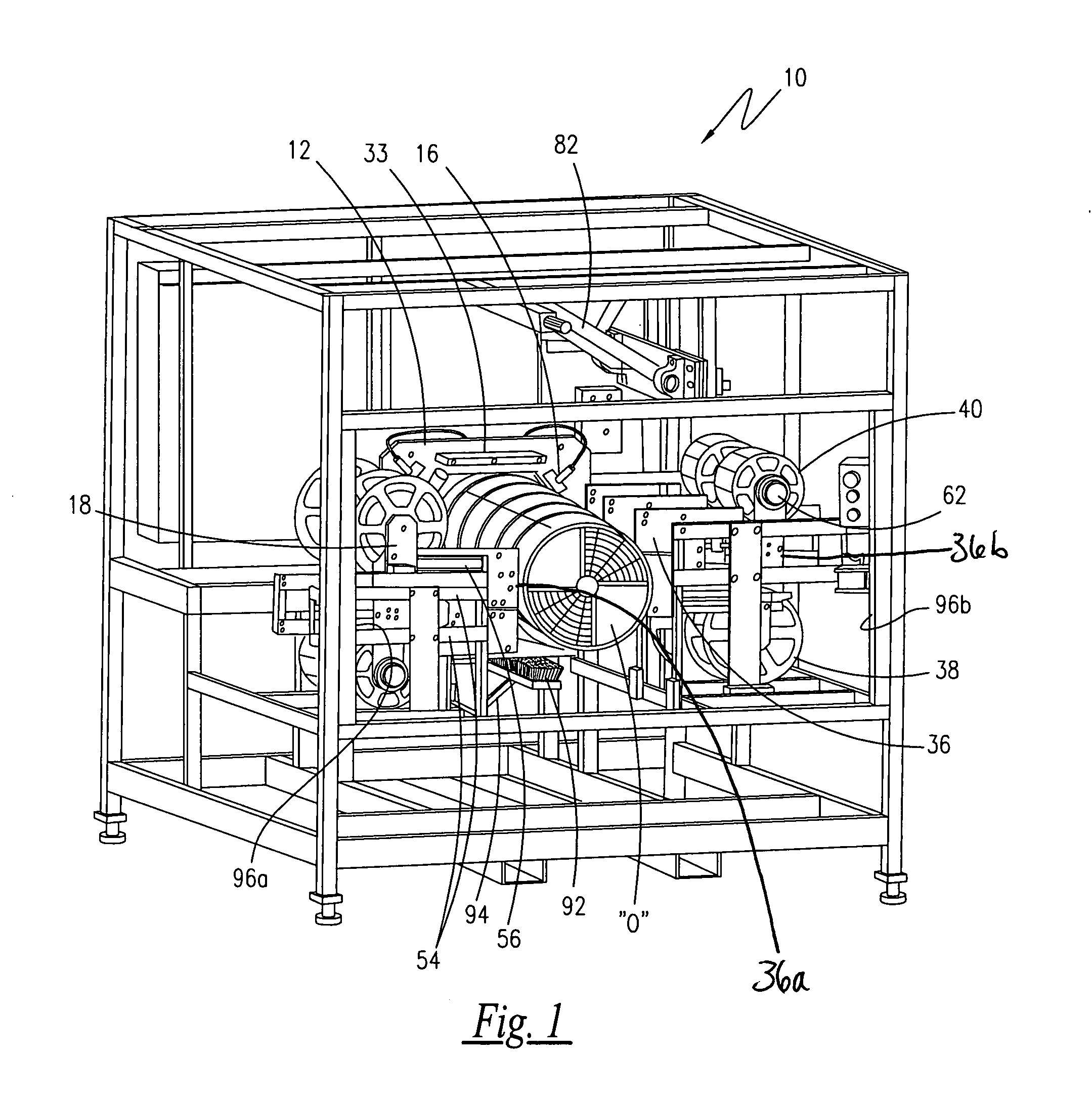
[0017]It is another feature of the present invention to provide an apparatus having a mandrel outwardly projecting from and substantially perpendicular to the base. The mandrel is envisioned as having a variety of lengths and diameters to provide versatility in accommodating variously dimensioned objects. It is envisioned that the mandrel is dimensioned so as to compliment the internal area of an object, such as a drum, a barrel, a stepped cone or other similar devices of varying lengths and widths. However, it should be noted that the object can have only a slight draft angle for moldability, because if the draft angle is too great on the object, the strip material will not track properly and wrinkles and air pockets will form. It is further envisioned that the mandrel is tapered from a fixed end to a free end (widest width at fixed end and narrowest width at free end). The tapering may be configured to have a uniformly gradual taper, such as similar to a cone. The tapering may also be configured to have a stepped taper, wherein at specified lengths of the mandrel, the exterior circumference is offset toward a center or central axis of the base and mandrel, so that a series of steps are formed (from a widest width at fixed end to a narrow width at free end). It is further envisioned that the mandrel comprises a plurality of openings formed at the free end substantially perpendicular to the central axis. As indicated previously, the openings operate cooperatively with openings to prevent formation of vacuum pressure on object during application of strip material.
[0020]It is another feature of the present invention to provide an apparatus further comprising a direct plasma flame treatment member, wherein the direct plasma flame treatment member generates a flame for evaporating liquid residue left from fabrication of the object. Furthermore, the direct plasma flame treatment of the object warms the object to activate any adhesive provided on the strip material, thereby optimizing the adhesion between the strip material and the object.
[0021]It is another feature of the present invention to provide an apparatus further comprising a brush head, wherein the brush head is used to firmly press the applied strip material against the object, thereby removing any air pockets that may have formed during application, and further optimizing adhesion between the strip material and the object.
[0022]It is another feature of the present invention to provide an apparatus further comprising a visual detector / curtain, in conjunction with full perimeter guarding where access is not required, wherein a pair of detectors are affixed at a front of the apparatus, wherein unauthorized penetration of an item (such as an operator's arm, leg, a tool or other flying debris) breaks a beam between the detectors and automatically terminates the application cycle. This automatic termination prevents injury to an operator, damage to tools, damage to the apparatus, and ensures the safe operation of the apparatus, in general.

Problems solved by technology

However, it should be noted that the object can have only a slight draft angle for moldability, because if the draft angle is too great on the object, the strip material will not track properly and wrinkles and air pockets will form.

Method used


Image

  • Strip material applicator apparatus
  • Strip material applicator apparatus
  • Strip material applicator apparatus

Examples


Embodiment Construction

[0033]The best mode for carrying out the invention is presented in terms of its preferred embodiment, herein depicted within FIGS. 1 through 6.

1. Detailed Description of the Figures

[0034]Referring to FIG. 1, an apparatus for applying strip material to an object 10 (hereinafter “apparatus”) is shown in accordance with a preferred embodiment of the present invention. The apparatus 10 comprises a base 12 having a mandrel 14 for supporting the object “O”, the mandrel 14 projecting from the base 12, a plurality of clamps 16 selectively movable for engaging and maintaining the position of the object “O”, the plurality of clamps 16 affixed to the base 12, and at least one strip material applicator assembly 18 selectively movable for engaging and applying strip material “S” onto the object “O” as the base 12 rotates. The base 12 rotates via a motor 20 integrally coupled thereto.

[0035]Referring now to FIG. 2, the motor 20 is a standard motor package commonly known in the art, and includes a ...


PUM

PropertyMeasurementUnit
Angleaaaaaaaaaa
Diameteraaaaaaaaaa
Lengthaaaaaaaaaa

Abstract

An apparatus for application of strip material to an object comprises a base supporting and mechanically rotating a mandrel projected therefrom, wherein an object is seated onto the mandrel. The object is securely held to the mandrel by a plurality of clamps engaging and impinging the object thereto. At least one applicator assembly is urged forward to apply strip material to the object, each applicator assembly comprising a material spool for dispensing strip material and a back spool for collecting strip material backing separated from the strip material during application. After application of the strip material, an arm and scalpel sever the strip material, and the applicator assembly pivots to apply the remaining end portion of the strip material.

Description

RELATED APPLICATIONS[0001]This application claims the benefit of U.S. Provisional Application Ser. No. 60 / 432,105 filed on Dec. 10, 2002, the disclosure of which is hereby incorporated by reference as if fully rewritten.BACKGROUND OF THE INVENTION[0002]1. Field of the Invention[0003]The present invention relates generally to a device for applying a strip of material to an object and, more particularly, to a device for applying a strip of adhesive tape or reflective sheeting to an object that is rotated on a mandrel and in communication with at least one tape or sheeting head.[0004]2. Description of the Related Art[0005]A number of devices have been constructed for applying bands of metal, tape, adhesive or other similar materials to polygonal bodies. At least three general embodiments representative of such devices are found in U.S. Pat. Nos. 3,899,383 and 4,009,072 (issued in the name of Schultz et al.) and U.S. Pat. No. 2,575,887 (issued in the name of Nitchie).[0006]In the patent...

Claims


Application Information

Patent Timeline
IPC IPC(8): B32B37/00B29C53/82B65H81/00
CPCB29C63/06B29C65/7847B29C66/5346B29C66/872B29L2011/0083B29C66/24221B29C66/1122
Inventor YERIAN, DIRKBAILOR, MARLINBAILEY, CARTERDIMASSA, DANIEL
Owner BERRAN INDAL GROUP
Learn More