Structure of air-packing device

a technology of air-packing device and structure, which is applied in the direction of packaging, flexible containers, sacks, etc., can solve the problems of not being able to recycle styroform, unable to produce soot, and unable to remove flake or chip, so as to prevent the reverse flow of air, prevent the effect of mechanical shock or vibration of the product and simple structur

Inactive Publication Date: 2007-01-23
AIR PAQ
View PDF11 Cites 59 Cited by
  • Summary
  • Abstract
  • Description
  • Claims
  • Application Information

AI Technical Summary

Benefits of technology

[0009]It is, therefore, an object of the present invention to provide a structure of an air-packing device for packing a product that can minimize a mechanical shock or vibration to the product by covering the whole product.
[0010]It is another object of the present invention to provide a structure of a check valve for the air-packing device that can reliably prevent reverse flow of the air in the air containers of the air-packing device.
[0012]It is a further object of the present invention to provide a structure of a check valve for the air-packing device that can enable to inflate the air-packing device with relatively low air pressure.
[0018]According to the present invention, the air-packing device can minimize a mechanical shock or vibration to the product when the product is dropped or collided. The sheet form of the air-packing device is folded and the post heat-seal treatment is applied thereto, thereby creating a structure unique to a production to be protected. The check valves in the air-packing device have a unique structure for preventing reverse flows of the air. The air-packing device of the present invention has a relatively simple structure with reliable check valves, it is able to provide a reliable air-packing device at low cost.

Problems solved by technology

Although the styroform package material has a merit such as a good thermal insulation performance and a light weight, it has also various disadvantages: recycling the styroform is not possible, soot is produced when it burns, a flake or chip comes off when it is snagged because of it's brittleness, an expensive mold is needed for its production, and a relatively large warehouse is necessary to store it.
Third, the air-packing device does not produce a chip or dust which may have adverse effects on precision products.

Method used


Image

  • Structure of air-packing device
  • Structure of air-packing device
  • Structure of air-packing device

Examples


Embodiment Construction

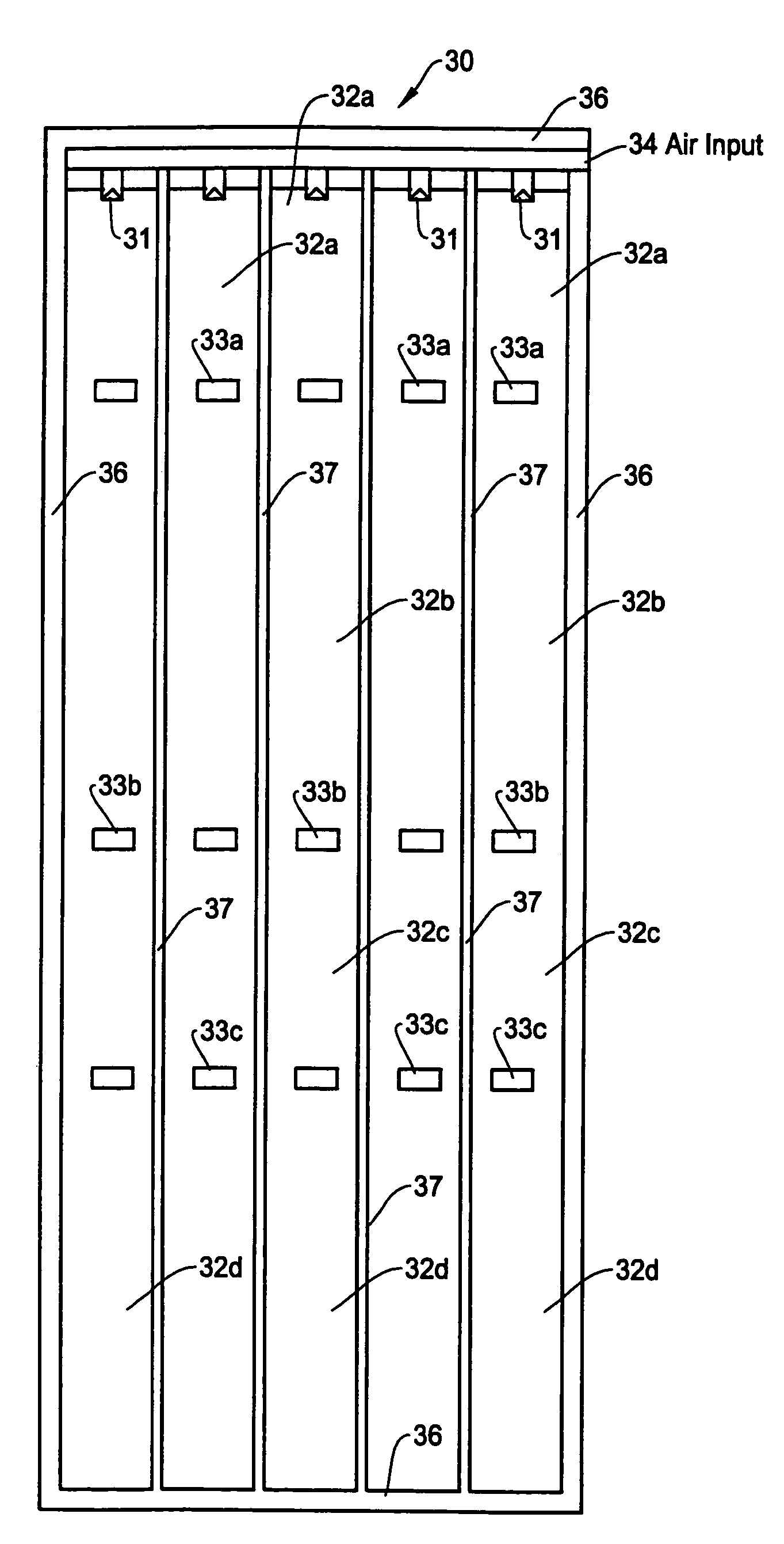
[0034]The air-packing device of the present invention will be described in more detail with reference to the accompanying drawings. It should be noted that although the present invention is described for the case of using air for inflating the air-packing device for an illustration purpose, other fluids such as other types of gas or liquid can also be used. The air-packing device is typically used in a container box to pack a product during the distribution flow of the product.

[0035]The air-packing device of the present invention is especially useful for packing a product which is sensitive to shock or vibration such as a personal computer, DVD driver, etc, having high precision mechanical components such as a hard disc driver. Other examples of such products include wine bottles, glassware, ceramic ware, music instruments, paintings, antiques, etc. The air-packing device reliably wraps the product within a space created by folding and applying a post heat-sealing treatment, thereby...


PUM


Abstract

An air-packing device has an improved shock absorbing capability to protect a product in a container box. The air-packing device is configured by first and second plastic films which are bonded at predetermined portions thereby creating a plurality of air containers, each of the air containers having a plurality of series connected air cells; a plurality of check valves established at inputs of the corresponding air containers for allowing compressed air to flow only in a forward direction; and an air input commonly connected to the plurality of check valves. Through a post heat-seal treatments, predetermined edge portions are bonded, thereby creating an inner space for packing a product therein and an opening for loading the product therethrough.

Description

FIELD OF THE INVENTION[0001]This invention relates to a structure of an air-packing device for use as packing material, and more particularly, to a structure of an air-packing device and check valves incorporated therein for achieving an improved shock absorbing capability to protect a product from a shock or impact occurred in a product distribution process.BACKGROUND OF THE INVENTION[0002]In a distribution channel such as product shipping, a styroform packing material has been used for a long time for packing commodity and industrial products. Although the styroform package material has a merit such as a good thermal insulation performance and a light weight, it has also various disadvantages: recycling the styroform is not possible, soot is produced when it burns, a flake or chip comes off when it is snagged because of it's brittleness, an expensive mold is needed for its production, and a relatively large warehouse is necessary to store it.[0003]Therefore, to solve such problems...

Claims


Application Information

Patent Timeline
Patent Type & Authority Patents(United States)
IPC IPC(8): B65D81/02
CPCB65D81/052
Inventor TANAKA, YASUZUMIYOSHIFUSA, KATSUTOSHI
Owner AIR PAQ
Why Eureka
Try Eureka