Optical system with angular compensator

a compensator and optical system technology, applied in the field of optical systems with angular compensators, can solve the problems of affecting the brightness of the pixel, changing the system performance, and angular dependence of the retardation of the lc material, so as to achieve the desired brightness for each pixel, improve contrast, and improve the effect of contrast uniformity

Active Publication Date: 2007-01-23
OMNIVISION TECH INC
View PDF22 Cites 5 Cited by
  • Summary
  • Abstract
  • Description
  • Claims
  • Application Information

AI Technical Summary

Benefits of technology

[0013]It is an advantage of the present invention that variations in the retardation seen by each ray portion of a beam are neutralized by a compensator.
[0014]It is another advantage of the present invention that the intended brightness for each portion of an image is achieved.
[0015]It is still another advantage of the present invention that improved contrast can be achieved, since the angular dependence of the LC retardation will have been substantially compensated for.
[0016]It is still another advantage of the present invention that improved contrast uniformity across the display can be achieved, since there is no substantial differential brightness offset in different portions of a projected image caused by differences in the index of refraction to which such different portions may be subjected.
[0017]It is yet another advantage of the present invention that the desired brightness for each pixel is achieved, without unwanted variations or aberrations caused by the retardation of the liquid crystal display device.

Problems solved by technology

There are two problems associated with the angular dependence of the retardation of the LC material.
Note that any angular variation of the retardation will change the way in which the LCD modifies the polarization of light, and therefore will change the system performance, almost always in a negative fashion.
In general, this variance from perpendicularity will degrade the performance of the system, most noticeably by lowering the contrast.
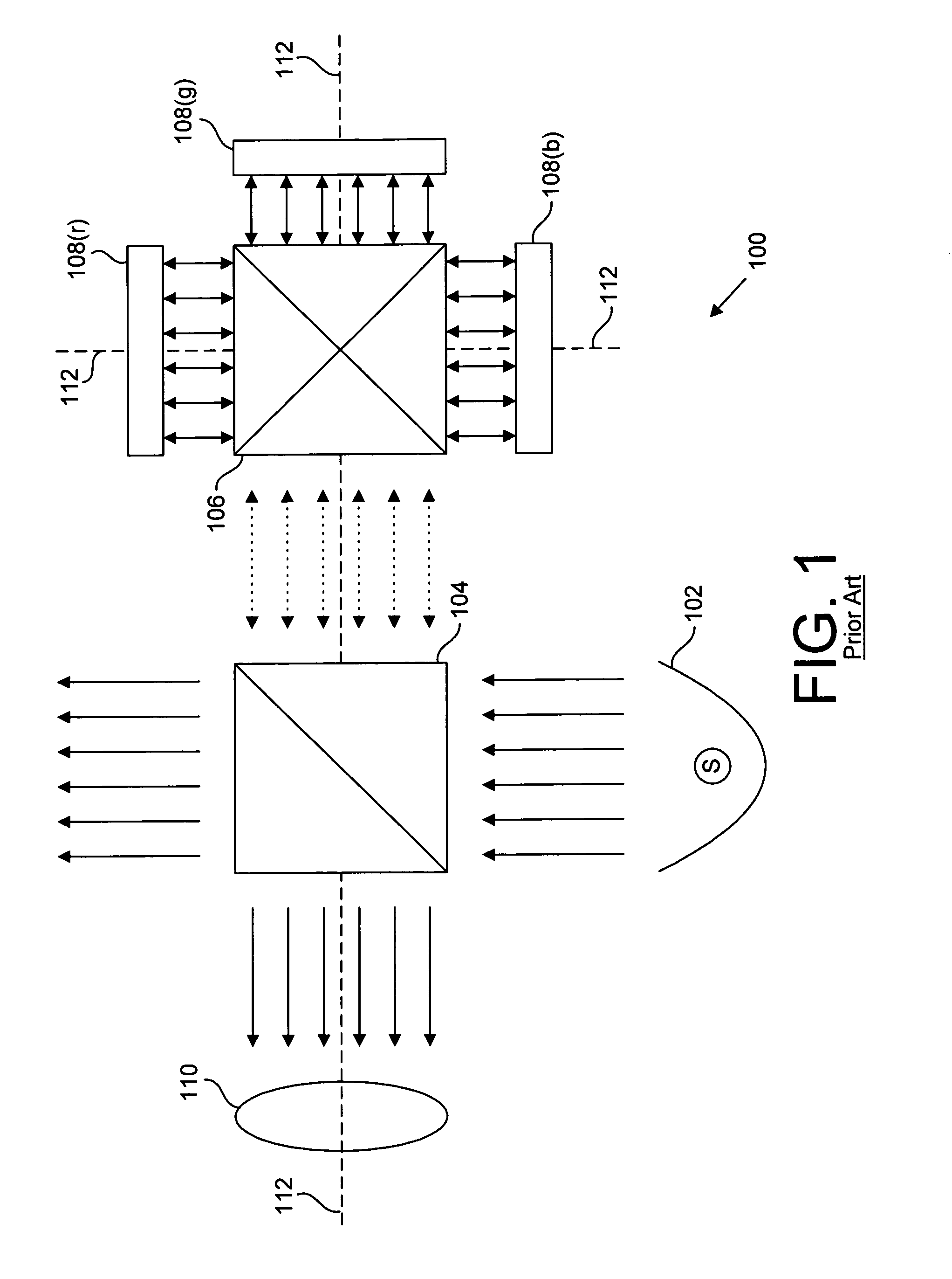
For the on axis design of FIG. 1, the center ray of this range of angles will be close to perpendicular at the LCD, but even in this case, there will be a degradation of performance because of the many non-perpendicular rays.
Secondly, such angular change will be different in different areas of the liquid crystal display apparatus.
Therefore, the undesired contrast shift discussed above will not be uniform across the entire liquid crystal display.

Method used


Image

  • Optical system with angular compensator
  • Optical system with angular compensator
  • Optical system with angular compensator

Examples


Embodiment Construction

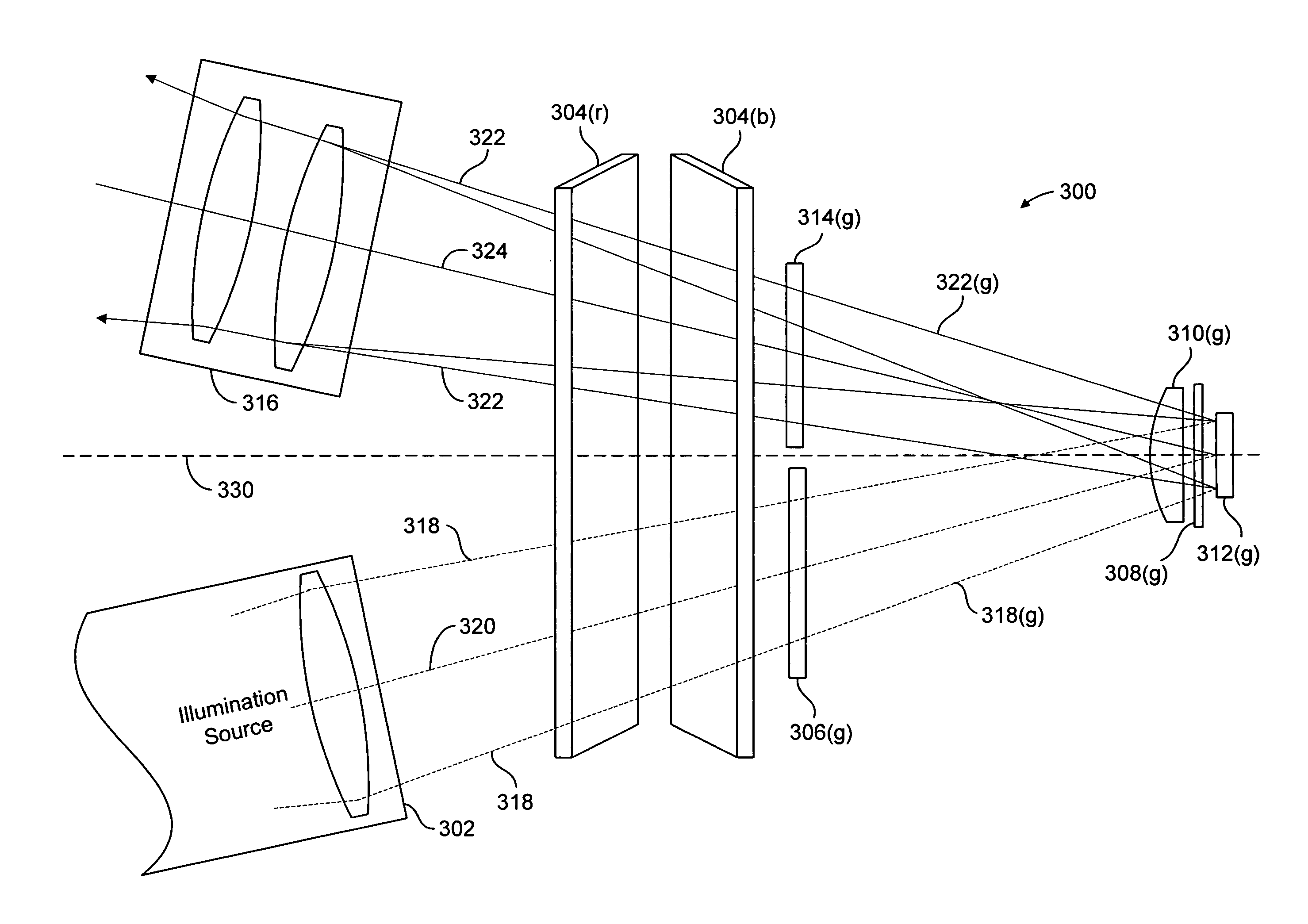
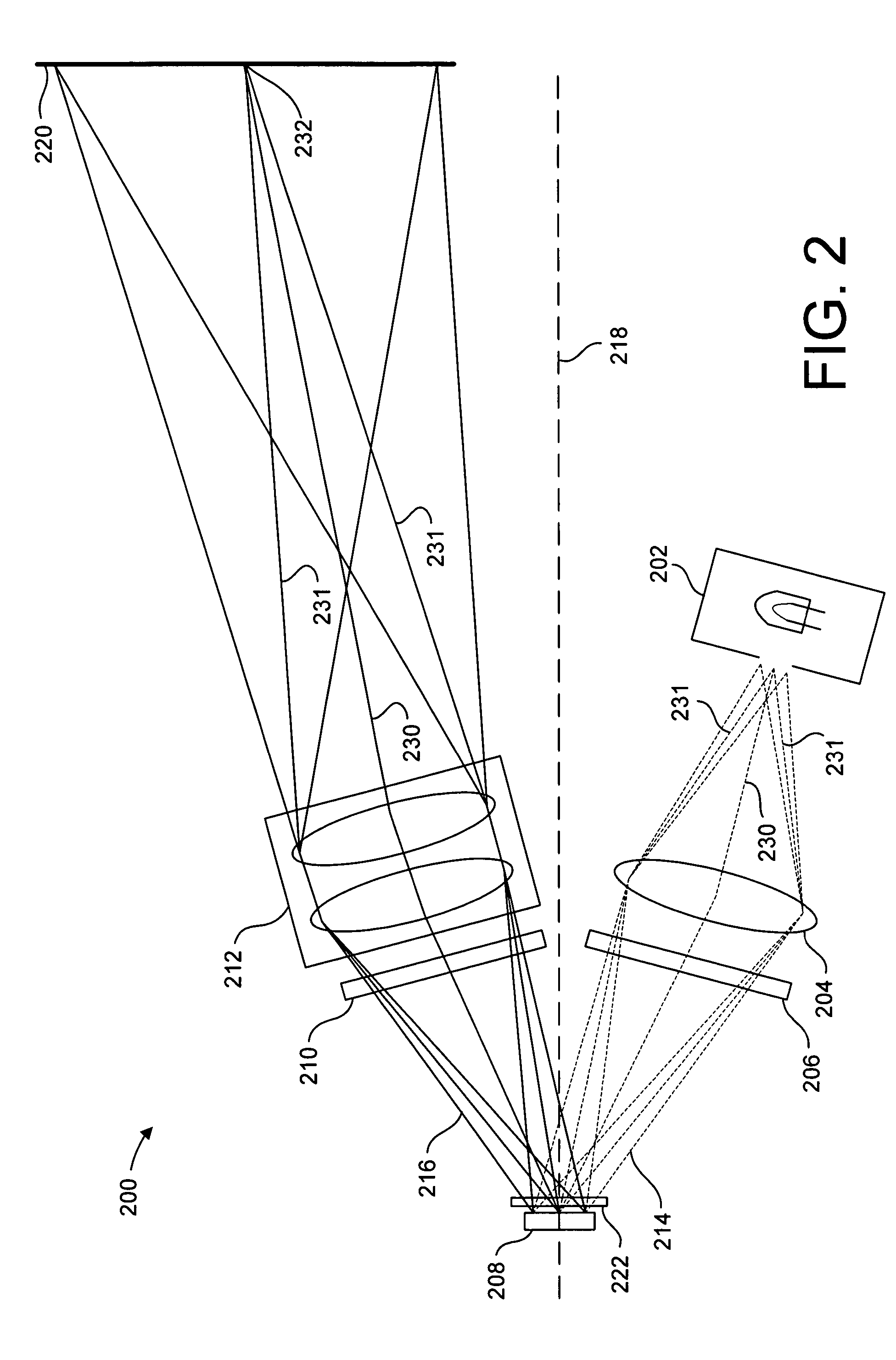
[0032]This invention is described in the following description with reference to the Figures, in which like numbers represent the same or similar elements. While this invention is described in terms of modes for achieving this invention's objectives, it will be appreciated by those skilled in the art that variations may be accomplished in view of these teachings without deviating from the spirit or scope of the present invention. The embodiments and variations of the invention described herein, and / or shown in the drawings, are presented by way of example only and are not limiting as to the scope of the invention. Unless otherwise specifically stated, individual aspects and components of the invention may be omitted or modified, or may have substituted therefore known equivalents, or as yet unknown substitutes such as may be developed in the future or such as may be found to be acceptable substitutes in the future. The invention may also be modified for a variety of applications whi...


PUM


Abstract

An electro-optical projection system includes a polarizer, a reflective light modulator, an analyzer, and a compensation element. The polarizer polarizes an illumination beam to form a polarized illumination beam. The reflective light modulator receives the polarized illumination beam along a first optical path, modulates the polarized illumination beam to form an imaging beam, and reflects the imaging beam along a second optical path. The compensation element is disposed in the polarized illumination beam and the imaging beam to compensate for polarization aberrations resulting from the birefringent property of the material of the reflective light modulator. The compensation plate has a retardation generally equal in magnitude and opposite in sign as compared to the retardation of the liquid crystal material of the reflective light modulator.

Description

BACKGROUND OF THE INVENTION[0001]1. Field of the Invention[0002]This invention relates generally to liquid crystal display devices, and more particularly to a method and apparatus for preventing unwanted reduction of contrast in images created thereby. A predominant current usage of the inventive improved optical system with angular compensation is in the correction of angularly dependent error caused by birefringence in reflective liquid crystal display devices, particularly but not exclusively in off axis optical systems, wherein angular dependant differences in the index of refraction will tend to create unintended changes in the brightness of an image.[0003]2. Description of the Background Art[0004]In a liquid crystal display (LCD”) imaging apparatus, it is important to carefully regulate the amount of light which forms each pixel of a displayed image, so as to provide the correct amount of contrast between lighter and darker portions of an image.[0005]FIG. 1. is a block diagram...

Claims


Application Information

Patent Timeline
Patent Type & Authority Patents(United States)
IPC IPC(8): G03B21/14G02B27/14H04N5/74H04N9/31
CPCG02B27/1026H04N5/7441H04N9/3197H04N9/3167H04N9/3105
Inventor FLYNN, MARK F.BONE, MATTHEW F.
Owner OMNIVISION TECH INC
Why Eureka
Try Eureka