
Reflecting mirror and its fabrication method

Inactive Publication Date: 2007-01-23
LIU CHENG SHUN
View PDF4 Cites 3 Cited by
  • Summary
  • Abstract
  • Description
  • Claims
  • Application Information

AI Technical Summary

Benefits of technology

[0001]The present invention relates to the manufacturing of a reflecting mirror and more particularly to a reflecting mirror fabrication method, which saves much labor and manufacturing time and, is practical to provide a safety reflecting mirror.
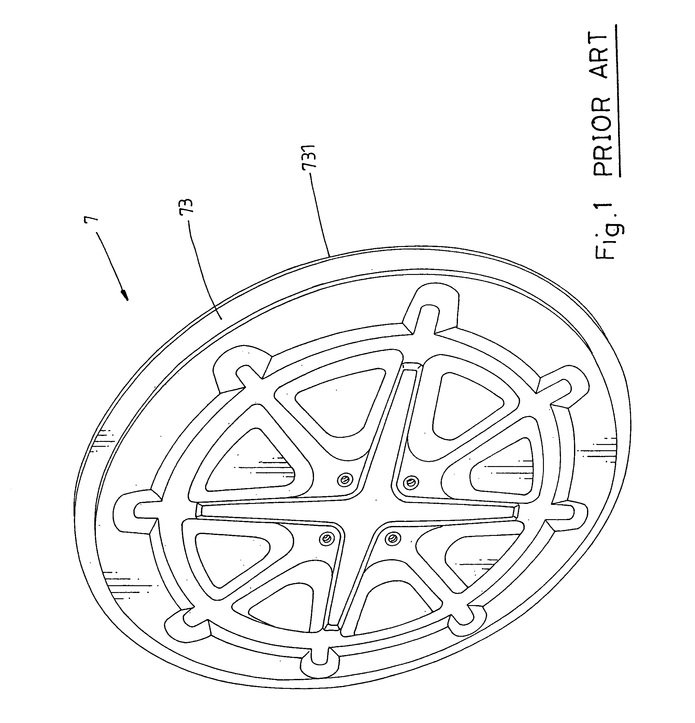
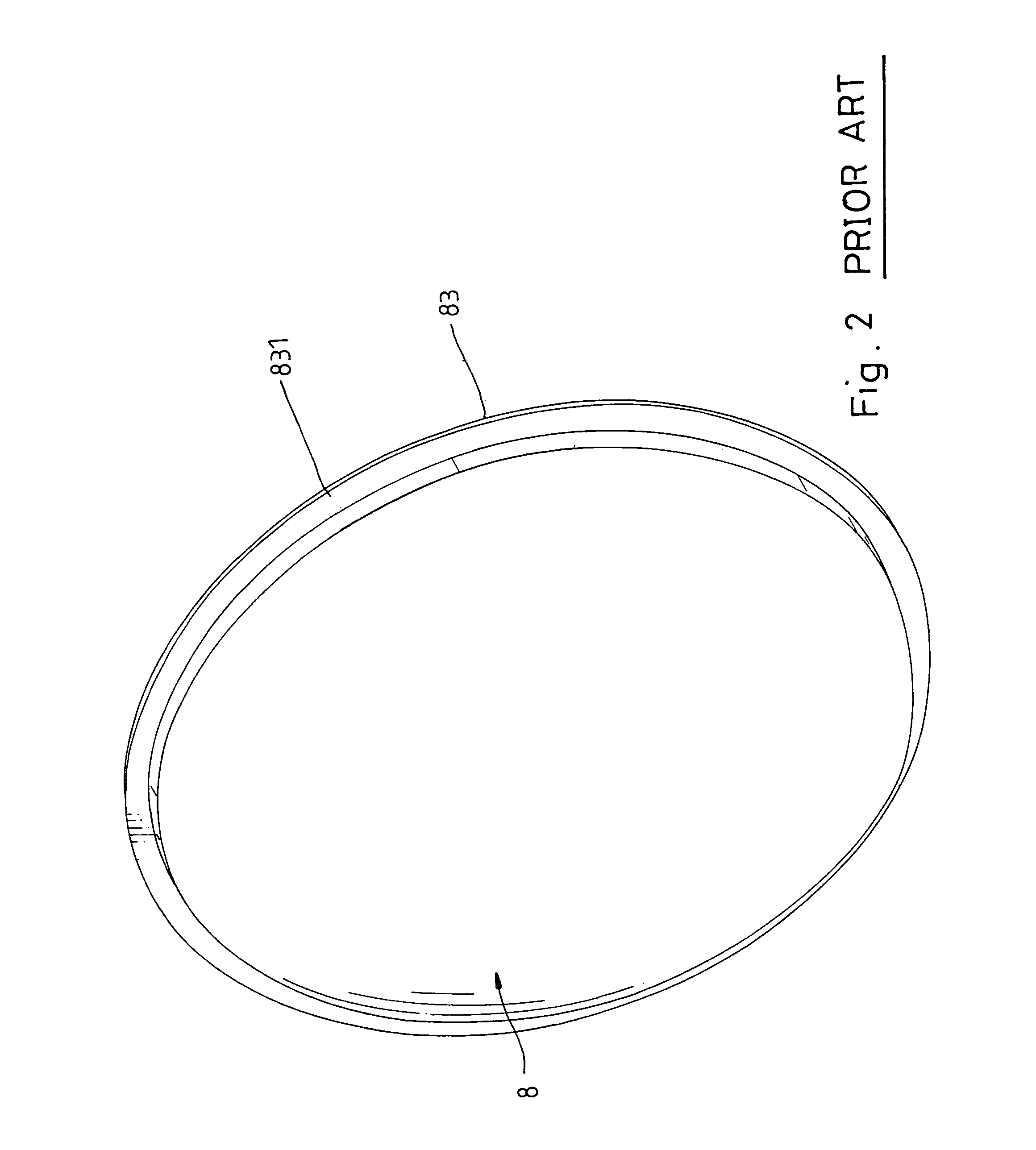
[0004]1. The use of the packing member 80 greatly complicates the manufacturing process of the reflecting mirror, and the peripheral edge 731 of the rim 73 of the back panel 7 or the peripheral edge 831 of the rim 83 of the mirror 8 may injure the worker accidentally.
[0007]The present invention has been accomplished under the circumstances in view. It is therefore one object of the present invention to provide a reflecting mirror fabrication method, which is practical to make a safety reflecting mirror that does not injure any person who touches the peripheral edge of the reflecting mirror accidentally. It is another object of the present invention to provide a reflecting mirror fabrication method, which saves much labor and manufacturing time. It is still another object of the present invention to provide a reflecting mirror fabrication method, which eliminates the use of any plastic materials

Problems solved by technology

This structure of reflecting mirror is functional, however it is not environmentally protective because of the use of a plastic material.

Method used


Image

  • Reflecting mirror and its fabrication method
  • Reflecting mirror and its fabrication method
  • Reflecting mirror and its fabrication method

Examples


Embodiment Construction

[0028]Referring to FIGS. 7˜15, a reflecting mirror fabrication method in accordance with the present invention includes the steps of:

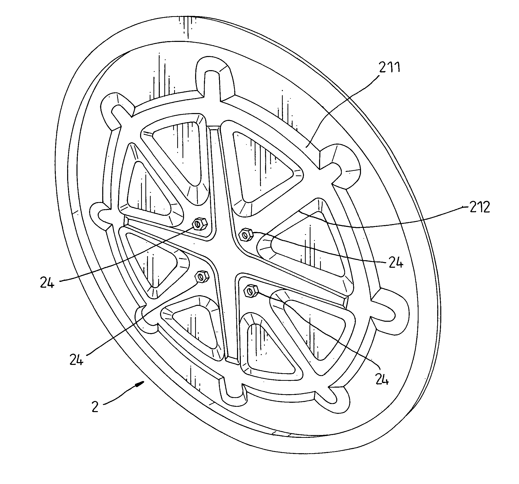
[0029](i) back panel formation 1 where a steel plate 11 is fed into a hydraulic press 12 and stamped by the hydraulic press 12 into a back panel 2 (see FIG. 8) subject to a predetermined pattern, which back panel 2 comprising a base 21, a plurality of reinforcing ribs 211 and 212 formed on the base 21, a rim 23 extending around the base 21, and an annular step 22 extending around the base 21 and connected between the base 21 and the rim 23;

[0030](ii) nut mounting process 3 where a plurality of screw nuts 24 are fixedly fastened to the back side of the base 21 at predetermined locations by spot welding (see FIG. 9);

[0031](iii) mirror formation 4 where a steel plate 41 is fed into a hydraulic press 42 and stamped into a mirror 5, which has a diameter relatively smaller than the back panel 2, a rounded base 51, a rim 53, which extends around the rounded b...


PUM


Abstract

A reflecting mirror fabrication method, which includes the steps of (a) stamping a steel plate into a back panel, which has a rib-reinforced base, a rim extending around the rib-reinforced base, (b) installing nuts in the back side of the back panel for mounting, (c) stamping a steel plate into a mirror, which has a rounded base, a rim extending around the rounded base, and an annular connected between the rounded base and the rim, and (d) roller ramming the rim of the back panel into a scrolled holding down rim portion to affix the rim of the mirror to the rim of the back panel.

Description

BACKGROUND AND SUMMARY OF THE INVENTION[0001]The present invention relates to the manufacturing of a reflecting mirror and more particularly to a reflecting mirror fabrication method, which saves much labor and manufacturing time and, is practical to provide a safety reflecting mirror.[0002]U.S. Pat. No. 5,909,327 discloses a reflecting mirror entitled “convex lens assembly”, which uses a plastic a back board to hold a convex lens. This structure of reflecting mirror is functional, however it is not environmentally protective because of the use of a plastic material.[0003]FIGS. 1˜6 show the fabrication of another design of reflecting mirror according to the prior art. According to this design, a galvanized steel plate and a stainless steel plate are respectively processed into a back panel 7 (see FIG. 1) and a mirror 8 (see FIG. 2). After the formation of the back panel 7, nuts 74 are fixedly fastened to the back side of the back panel 7 (see FIG. 3), and a visor 85 is fixedly faste...

Claims


Application Information

Patent Timeline
IPC IPC(8): G02B7/182A47F1/14
CPCG02B5/08G02B7/182Y10S359/90
Inventor LIU, CHENG-SHUN
Owner LIU CHENG SHUN
Learn More