Position sensor utilizing a linear hall-effect sensor

a technology of hall-effect sensor and position sensor, which is applied in the field of position sensors, can solve problems affecting the overall performance of the sensor, and achieve the effect of improving the control and linearity of the flux density versus stroke characteristics

Active Publication Date: 2007-01-23
BEI SENSORS & SYST
View PDF17 Cites 15 Cited by
  • Summary
  • Abstract
  • Description
  • Claims
  • Application Information

AI Technical Summary

Benefits of technology

[0011]The magnetic field assembly of the present invention is suitable for linear as well as rotary sensor applications. In a linear application context the first and second magnets may have sides which are transverse to the surface of the magnetic plate and substantially parallel to the stroke direction of the position sensor. In a rotary sensor application context, the position sensor may have an angular stroke, and the first and second magnets may have sides which are transverse to the surface of the magnetic plate and arc-shaped along the angular stroke. In the rotary sensor application context, the first and second magnets may have a width dimension which varies along the stroke direction of the position sensor.
[0012]A position sensor in accordance with the present invention includes a field assembly as described in the foregoing, and a magnetic sensor, such as a Hall-effect sensor.
[0013]It is therefore an object of the present invention to provide a method for and apparatus in which a field assembly is configured by varying the thickness of first and second magnets which are positioned apart from one another on a magnetic plate, and selecting the separation distance between the magnets, and the gap length distance, so that a desired flux density versus stroke is provided.
[0014]It is a further object of the present invention to provide a method for configuring, and a position sensor apparatus, in which first and second magnets of a field assembly are positioned on a magnetic plate at a separation distance apart, and the thickness of each magnet is varied so that each magnet provides a planar surface which faces a magnetic sensor, and which are angled at an acute angle.

Problems solved by technology

It is believed that with such a configuration, the disclosed sensor operates only on leakage flux from the magnet, which in turn affects the overall performance of the sensor.

Method used


Image

  • Position sensor utilizing a linear hall-effect sensor
  • Position sensor utilizing a linear hall-effect sensor
  • Position sensor utilizing a linear hall-effect sensor

Examples


Embodiment Construction

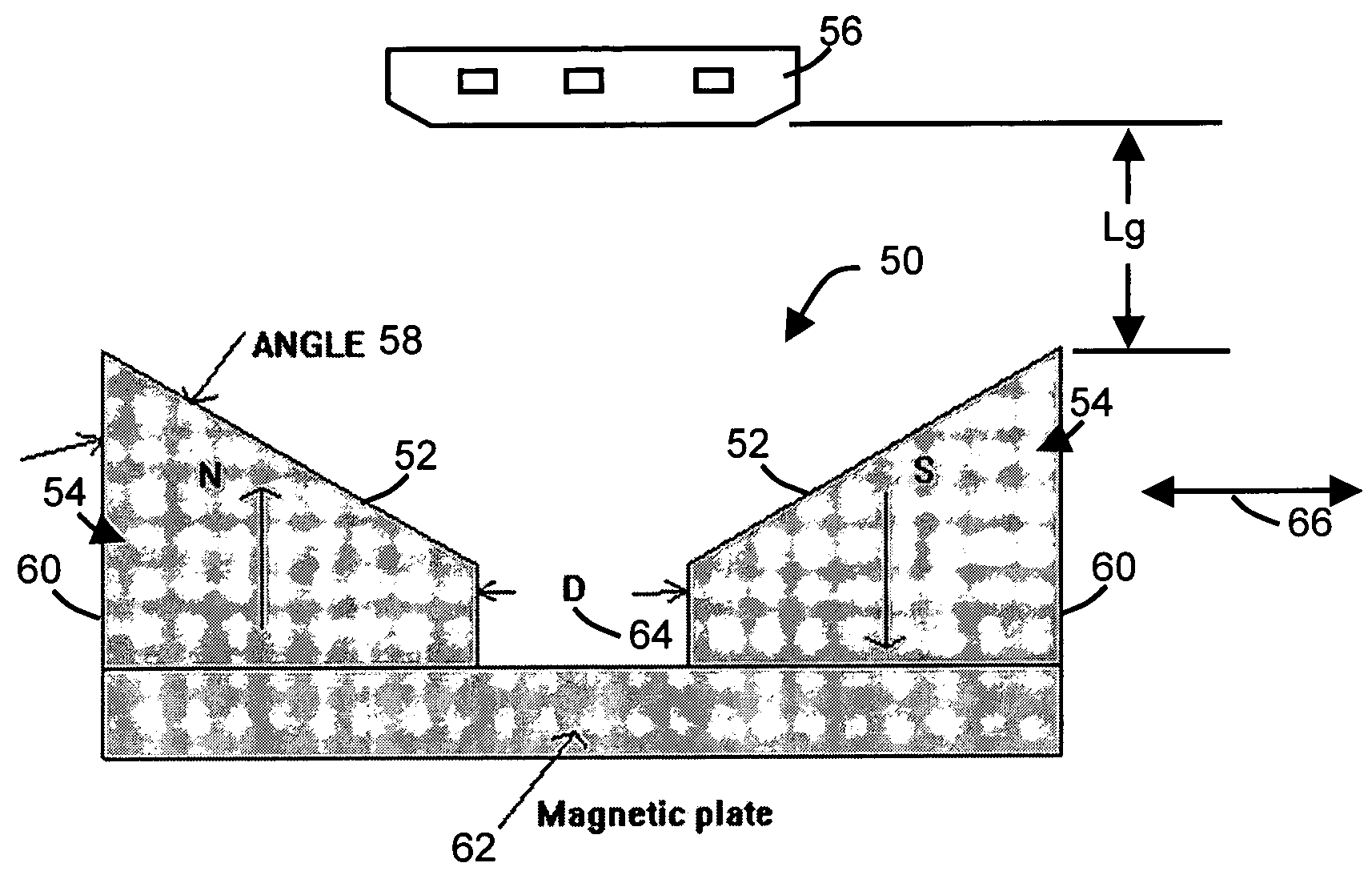
[0026]Referring now to FIG. 4, a position sensor in accordance with the present invention is illustrated. In particular there is shown a cross section of a magnetic field assembly 50 of a position sensor utilizing a linear Hall-effect sensor which provides improved linearity in accordance with the present invention. As can be seen from FIG. 4, the sides 52 (of the magnets 54) which face the Hall-effect sensor 56 are formed at an angle 58 with respect to the vertical sides 60 of the magnets 54. The angle 58 is preferably and acute angle relative to the vertical sides 60. Also, the magnets 54 are positioned on magnetic plate 62 and spaced apart by a separation distance D (64). The direction of motion of the magnetic field assembly 50 is shown by arrow 66.

[0027]FIG. 5 depicts one example of the utilization of the illustrated embodiment of the position sensor of the present invention, where the magnet assembly 50 is attached to a hub 68, which, in turn, is put on a shaft of a motion dev...


PUM


Abstract

A magnetic field assembly and method of configuring the same for use in position sensors of the type which include a magnetic field sensor. First and second magnets in the field assembly are positioned on a surface of a magnetic plate (return path) and separated from one another by a separation distance. The first magnet has a magnetic axis substantially transverse to the surface of the magnetic plate, and the first magnet has a polarity opposite a polarity of the second magnet. The thicknesses of the first and second magnets are selectively varied along a stroke direction, and the separation distance is selected along with a gap length distance between the magnetic sensor and the field assembly, so that a predetermined flux density versus stroke characteristic can be provided for the position sensor.

Description

RELATED APPLICATIONS[0001]The present application claims priority under 35 U.S.C. §119(e) from provisional application No. 60 / 447,798, filed Feb. 14, 2003.TECHNICAL FIELD[0002]The present invention is directed generally to position sensors, and in particular to a position sensor in which magnet thicknesses and separation are varied to provide desired flux density versus stroke characteristics.BACKGROUND ART[0003]Typical linear position sensors are described in an applications information publication entitled, “Linear Hall-Effect Sensors” by Allegro MicroSystems, Inc. of Worcester, Mass. Such linear position sensors are depicted in FIG. 1, for example, which is a drawing excerpted from the aforementioned publication. Each of these position sensors consists of a magnet field assembly 20 and a linear Hall-effect sensor 22. Magnetic field assembly 20 is comprised of two or four rectangular magnets 24 and soft magnetic housing 26. Linear Hall-effect sensor 22 crosses the magnetic field c...

Claims


Application Information

Patent Timeline
Patent Type & Authority Patents(United States)
IPC IPC(8): G01B7/14G01R33/07H01L43/06G01B7/30G01D5/14G01R
CPCG01D5/145G01D2205/18G01B7/003G01B7/30
Inventor GODKIN, MIKHAIL
Owner BEI SENSORS & SYST
Why Eureka
Try Eureka