Method and device for transmission with reduced crosstalk

a transmission device and crosstalk technology, applied in the field of methods and devices for transmission with reduced crosstalk, can solve the problems of not being able to describe all interconnections, not having specific physical characteristics, and being economically disadvantageous

Inactive Publication Date: 2007-01-23
RAMBUS INC +1
View PDF8 Cites 123 Cited by
  • Summary
  • Abstract
  • Description
  • Claims
  • Application Information

AI Technical Summary

Benefits of technology

[0055]These properties show that the propagation of waves each corresponding to a single modal variable, produced with a suitable conversion in one of the transmitting circuits and used with an inverse conversion in one of the receiving circuits enables transmission without crosstalk between the channels.
[0074]The person skilled in the art knows, for instance, from a computation based on the geometry of the conductors and insulators, on the conductivity of the conductors and on the permittivity and the losses of the insulators, how to determine the natural matrices L, R, C and G of a multiconductor transmission line, as a function of frequency. The person skilled in the art also knows how to measure these matrices. It is therefore clear that it is possible to accurately determine the characteristic impedance matrix of the multiconductor transmission line in any frequency interval, up to the maximum frequency for which the transmission line theory is applicable. This maximum frequency depends on the cross dimensions of the interconnection, and the person skilled in the art knows that it corresponds to the appearance of the first non-evanescent propagation modes other than the quasi-TEM modes. In this same frequency interval, it is obviously also possible to determine a “transition matrix from modal voltages to natural voltages” S and / or a “transition matrix from modal currents to natural currents” T, as a function of frequency, so as to define modal voltages and / or modal currents.
[0085]means for optimizing the relative position of the transmission conductors by minimizing the error coefficients or coefficients.
[0094]In a device for implementing the method of the invention, it is possible to obtain the generation of m modal electrical variables at the output of a transmitting circuit.
[0121]The prior art required, for obtaining very low crosstalk on interconnections, that they have a complex three-dimensional structure, that they contain for instance a twisted pair for each channel, or a screen for each channel. According to the invention, reduced crosstalk may be obtained merely by creating an interconnection with parallel conductors, hence cutting down cost and size.

Problems solved by technology

However, a priori no specific physical characteristic distinguishes what we have called a transmission conductor (which some authors call a signal conductor) from the reference conductor.
Besides, this model is not capable of describing all interconnections.
The techniques of 1) and 2) above, which are often implemented on twisted pair cables, achieve excellent performance, but they require the use of two transmission conductors for each signal to be sent, which is economically disadvantageous.
They are difficult to implement beyond a few hundred megahertz.
The technique of 7) is also expensive.
The techniques of 3) and 4) above are efficient when used jointly, but this approach takes up room, a factor that is difficult to accept in current printed circuit boards as well as in cables.
One may say that these techniques are limited in the following manner: their performance levels are low, or they require a substantial cross dimension of the interconnection, because of the increased spacing of the transmission conductors, or because of the use of a much larger number of conductors (typically twice the number) than the number of signals to be sent.

Method used


Image

  • Method and device for transmission with reduced crosstalk
  • Method and device for transmission with reduced crosstalk
  • Method and device for transmission with reduced crosstalk

Examples


seventh embodiment

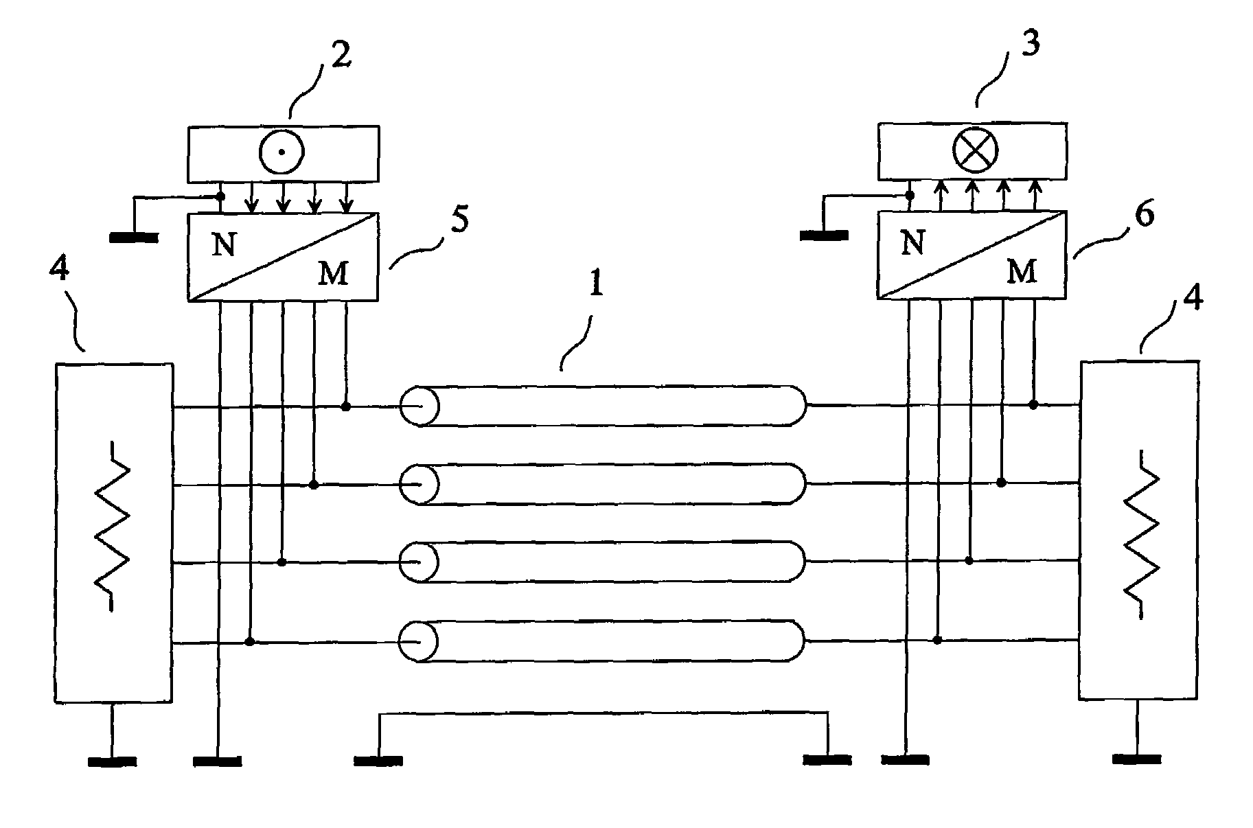
[0117]However, the connection of the transmitting circuits and / or the receiving circuits in parallel with the interconnection is not at all a characteristic of the invention. According to the invention, the transmitting circuit(s) and / or the receiving circuit(s) may be connected in series to the interconnection, in which case they must generally show a low series impedance to the interconnection, in order not to disturb the propagation of waves along the interconnection. a device of the invention, described below as an example, comprises a transmitting circuit connected in series to the interconnection.

[0118]A device of the invention may be such that the termination circuits, the transmitting circuit(s), and the receiving circuit(s) are without any part in common to any two of them.

[0119]Conversely, a device of the invention may be such that the termination circuits, the transmitting circuit(s), and the receiving circuit(s) are not without a part or parts common to any two of them. ...

first embodiment

[0126]FIG. 3 shows the invention;

second embodiment

[0127]FIG. 4 shows the invention (best mode);


PUM


Abstract

The invention relates to a method and a device for transmission with reduced crosstalk in interconnections used for sending a plurality of signals, such as the interconnections made with flat multiconductor cables, or with the tracks of a printed circuit board, or inside an integrated circuit. An interconnection with four parallel transmission conductors plus a reference conductor has each of its ends connected to a termination circuit. The transmitting circuit receives at its input the signals of the four channels of the source and its output terminals are connected to the conductors of the interconnection. The receiving circuit's input terminals are connected to the conductors of the interconnection, and its four output channels are connected to the destination. The signals of the four channels of the source are sent to the four channels of the destination, without noticeable crosstalk.

Description

CROSS REFERENCE TO RELATED APPLICATIONS[0001]This is the U.S. National Phase of PCT / EP2003 / 015036, filed Dec. 24, 2003, which in turn claims priority to French Application No. 03 / 00064, filed Jan. 6, 2003, both of which are incorporated herein in their entirety by reference.FIELD OF THE INVENTION[0002]The invention relates to a method and a device for transmission with reduced crosstalk through interconnections used for sending a plurality of signals, such as the ones made with flat multiconductor cables, or with the tracks of a printed circuit board, or inside an integrated circuit.[0003]The French patent application number 0300064 of 6 Jan. 2003, entitled “Procédé et dispositif pour la transmission avec une faible diaphonie” is incorporated by reference.PRIOR ART[0004]Let us first consider the theoretical problem of an interconnection with n transmission conductors placed close to a reference conductor. Let us number these conductors from 0 to n, where 0 is the “reference conducto...

Claims


Application Information

Patent Timeline
Patent Type & Authority Patents(United States)
IPC IPC(8): H03K17/16G09G3/20H01R3/00H04B3/28H04B3/32H04B3/46H04L5/20H04L25/02H04L25/08
CPCH04B3/32H04L5/20H04L25/0272H04L25/0278H04B3/487H04L25/0292H04L25/08H04L25/028Y10S439/941
Inventor BROYDE, FREDERICCLAVELIER, EVELYNE
Owner RAMBUS INC
Why Eureka
Try Eureka