Supercharge Your Innovation With Domain-Expert AI Agents!

Radar system and method for determining the height of an object

a technology of height and object, applied in the field of mapping an area using radar, can solve the problems of laser system inability to operate in low visibility conditions, laser system inability to assume in certain environments, and type of sweep used in laser scanning can be impractical in real beam radar system and other radar systems

Inactive Publication Date: 2007-01-23
THE BOEING CO
View PDF12 Cites 16 Cited by
  • Summary
  • Abstract
  • Description
  • Claims
  • Application Information

AI Technical Summary

Benefits of technology

This approach effectively determines object height with sufficient accuracy for autonomous vehicle navigation, providing a 3D map that can be used for obstacle detection and navigation, even in low visibility conditions, with the ability to operate in various environmental conditions.

Problems solved by technology

This assumption can be impractical in certain environments because different shapes reflect radar signals differently.
This type of sweep used in laser scanning can be impractical in real beam radar systems and other radar systems which do not employ lasers because the radar signal in real beam systems tend to have a very wide beam which does not allow sufficient accuracy and consistency to provide useful information regarding the height of the object.
Lasers systems cannot operate in low visibility conditions because they are based on a light beam, whereas radar systems of the proper design can operate in any conditions.
However, these IFSAR techniques do not result in sufficient information to consistently provide actual height information.
Also, IFSAR cannot be used on ground vehicles because it relies on doppler information integrated over time.
Ground vehicle guidance does not generate sufficient Doppler information over time for integrating.

Method used


Image

  • Radar system and method for determining the height of an object
  • Radar system and method for determining the height of an object
  • Radar system and method for determining the height of an object

Examples


Embodiment Construction

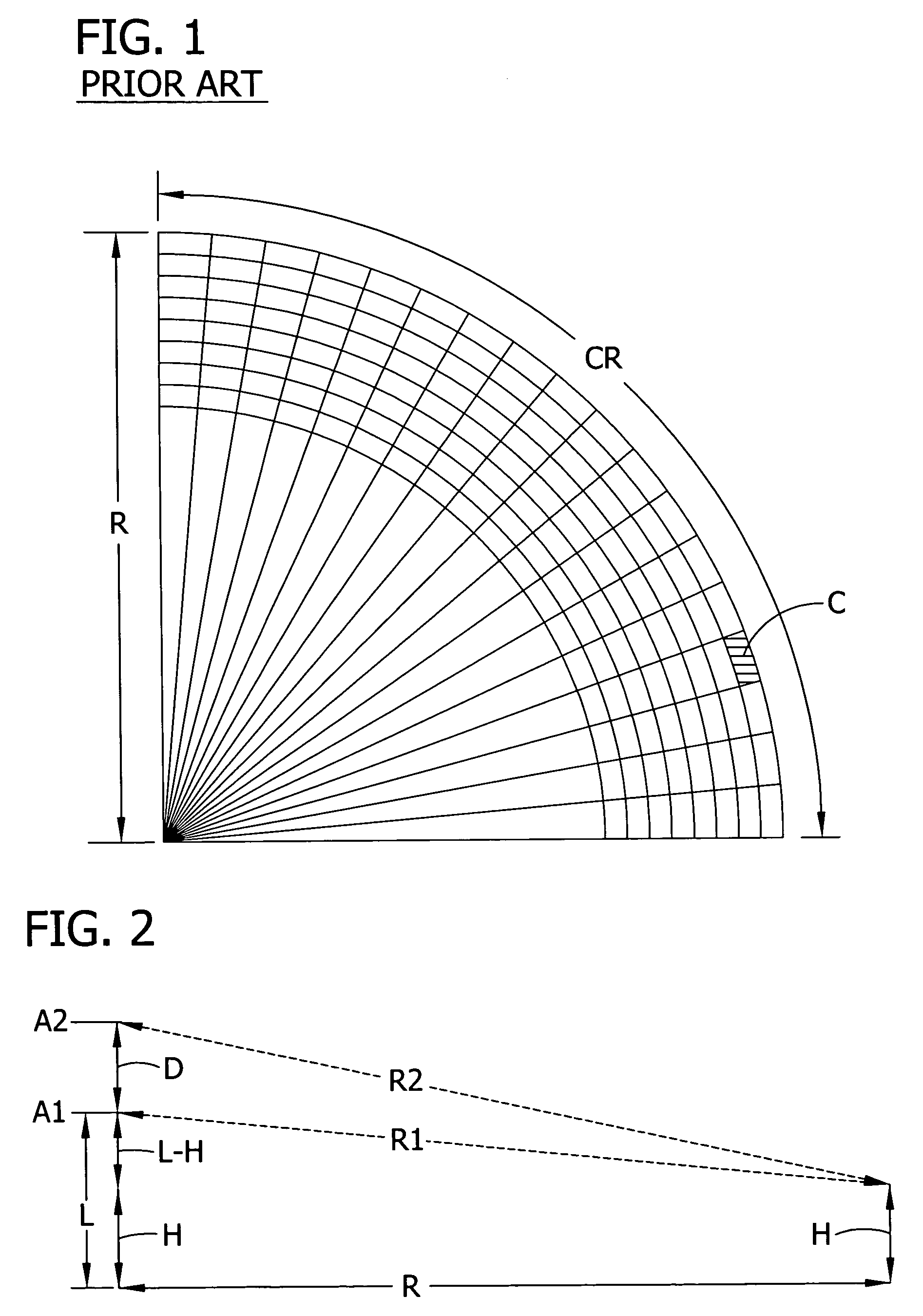
[0021]FIG. 1 illustrates a map created with a monostatic real beam radar system. The system simultaneously searches for objects within a range / crossrange cell about range R with a particular crossrange CR. The information from each scan is combined to identify objects within the cells of the grid in FIG. 1. In the case of real beam radar, according to the invention interferometry is implemented by combining a monostatic radar and an additional, vertically spaced antenna that receives the reflected signal in order to provide information about the height of objects in each cell.

[0022]In the present invention, a first antenna A1 transmits a real beam radar signal in one crossrange CR having target objects that reflect the signal. The first antenna A1 and a second antenna A2 vertically spaced from the first antenna A1 both receive the reflected real beam radar signal and provide corresponding antenna output signals. The phase difference between the two antenna output signals is extracte...


PUM


Abstract

System and method for determining the height of an object reflecting a real beam radar signal by receiving the reflected signal with a first and second vertically spaced antennas. Receivers provide two signals indicating the phase of the reflected signals received by the two antennas. A digital processor determines the phase difference between the two signals and calculates the object height.

Description

FIELD OF THE INVENTION[0001]The present invention generally relates to mapping an area using radar and, more particularly, to a radar system and method for producing a three-dimensional map of an area. Further, the invention relates to a real beam radar system and method for three-dimensional ground mapping for use in autonomous vehicle navigation.BACKGROUND OF THE INVENTION[0002]The use of radar in navigation allows mapping of sectors. For example, autonomous ground vehicle navigation has used radar to produce a two-dimensional map of the terrain ahead of the vehicle. Referring to FIG. 1, a grid comprising range RA and cross-range CR dimensions to define cells such as cell C has been employed to lay out the area in front of the vehicle. The difficulty of traversing an obstacle in a cell of the grid was assumed to be proportional to the amplitude of the returned radar signal from the cell. This assumption can be impractical in certain environments because different shapes reflect ra...

Claims


Application Information

Patent Timeline
Patent Type & Authority Patents(United States)
IPC IPC(8): G01S13/08G01S13/94G01S13/931G01S13/935
CPCG01S13/426G01S13/931G01S13/46G01S2013/9321
Inventor WITTENBERG, PETERMOSHER, AARON Y.
Owner THE BOEING CO
Features
  • R&D
  • Intellectual Property
  • Life Sciences
  • Materials
  • Tech Scout
  • Unparalleled Data Quality
  • Higher Quality Content
  • 60% Fewer Hallucinations
Learn More