Integrated multi-tuner satellite receiver architecture and associated method

a satellite receiver and multi-tuner technology, applied in the field of high-frequency transmission satellite receiver architectures, can solve the problems of 1/f noise from baseband circuitry, dc offset voltage noise, and the inability to design integrated circuit implementations that use ddc architectures. the effect of noise and interferen

Inactive Publication Date: 2007-01-23
SILICON LAB INC
View PDF51 Cites 37 Cited by
  • Summary
  • Abstract
  • Description
  • Claims
  • Application Information

AI Technical Summary

Benefits of technology

[0006]The present invention provides integrated multi-tuner receiver architectures and associated methods that utilize coarse analog tune circuitry to provide initial analog coarse tuning of desired channels within a received spectrum signal, such as transponder channels within a set-top box signal spectrum for satellite communications. These multi-tuner receiver architectures, as described in detail below, provide significant advantages over prior direct down-conversion (DDC) architectures and low intermediate-frequency (IF) architectures, particularly where two tuners are desired on the same integrated circuit. Rather than using a low-IF frequency or directly converting the desired channel frequency to DC, initial coarse tuning provided by analog coarse tuning circuitry allows for a conversion to a frequency range around DC. This coarse tuning circuitry can be implemented, for example, using a large-step local oscillator (LO) that provides a coarse tune analog mixing signal. Once mixed down, the desired channel may then be fine-tuned through digital processing, such as through the use of a wide-band analog-to-digital converter (ADC) or a narrow-band tunable bandpass ADC. The disclosed multi-tuner receiver architectures, therefore, have the efficiency of using a single mixing frequency while still avoiding interference and noise problems that plague DDC architectures.

Problems solved by technology

However, in practice, there are several issues that often prohibit the practical design of integrated circuit implementations that use DDC architectures.
These issues typically include noise from the DC offset voltage and 1 / f noise from baseband circuitry located on the integrated circuit.
In mobile applications, such as with cellular phones, the DC offset voltage is a time varying entity which makes its cancellation a very difficult task.
However, 1 / f noise is still an issue and often degrades CMOS satellite tuners that use a DDC architecture.
DDC architectures, however, suffer from disadvantages such as susceptibility to DC noise, 1 / f noise and I / Q path imbalances.
Such LC-based VCOs are often difficult to tune over wide frequency ranges and often are prone to magnetically pick up any magnetically radiated noise.
In addition, interference problems arise because the center frequency for the selected transponder channel and the DDC mixing signal are typically at the same frequency or are very close in frequency.
Furthermore, where two tuners are desired on the same integrated circuit, two DDC receivers, as well as two low-IF receivers, will have a tendency to interfere with each other, and their VCOs also have a tendency to inter-lock into one another, particularly where the selected transponder channels for each tuner are close together.

Method used


Image

  • Integrated multi-tuner satellite receiver architecture and associated method
  • Integrated multi-tuner satellite receiver architecture and associated method
  • Integrated multi-tuner satellite receiver architecture and associated method

Examples


embodiment 300

[0045]Looking to channel 308 in FIG. 3, it is located within the channel spectrum such that it overlaps the LO frequency for BIN2 and the boundary of BIN1 and BIN2, which are both designed to be located at about 1050 MHz. As discussed above with respect to FIG. 2C, the LO mixing frequency fLO2 would not be used to avoid a direct down conversion of channel 308 to DC. Rather, the LO mixing frequency fLO1 for BIN1 or the LO mixing frequency fLO3 for BIN3 could be used to mix down the channel 308. It is noted that by having overlapping frequency bins, an LO frequency closer to the center frequency for the desired channel 308 could be used. For example, if only the non-overlapping even numbered bins 322 were provided in the embodiment 300, the next adjacent LO mixing frequency would have been LO mixing frequency fLO4 for BIN4, which is 100 MHz from the LO mixing frequency fLO2 for BIN2, rather than the 50 MHz frequency step between the LO frequencies for BIN2 and BIN1 and for BIN2 and BI...

embodiment 500

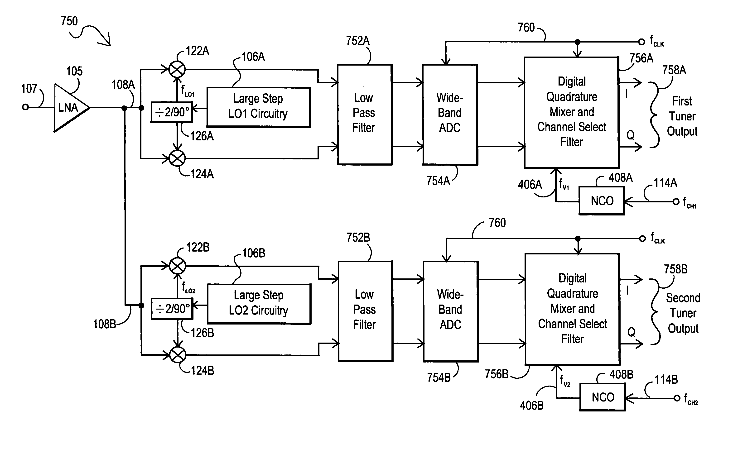
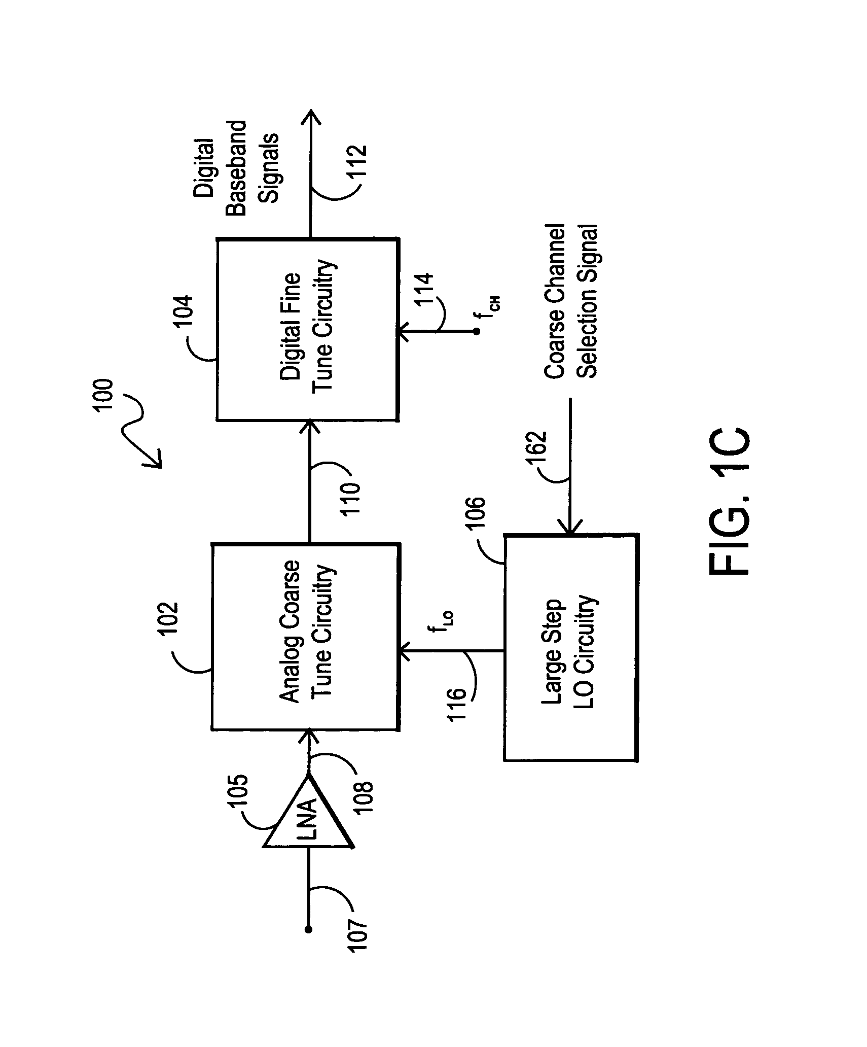
[0047]FIG. 5A is a block diagram of an embodiment 500 for a two receiver architecture located on a single integrated circuit. In general, this embodiment 500 duplicates the circuitry of FIG. 1C to produce a dual receiver architecture. The first receiver includes analog coarse tune circuitry 102A, large-step LO1 circuitry 106A (which outputs a first LO mixing frequency (fLO1)116A), and digital fine tune circuitry 104A (which receives a first center frequency (fCH1) 114A for a first desired channel to be tuned). As discussed above, the first receiver coarsely tunes the input channel spectrum 108A to produce the intermediate coarsely tuned channel signal 110A and then digitally processes this signal to finely tune the channel and to produce digital baseband signals for the first tuner output 112A. Similarly, the second receiver includes analog coarse tune circuitry 102B, large-step LO2 circuitry 106B (which outputs a second LO mixing frequency (fLO2)116B), and digital fine tune circuit...

embodiment 700

[0062]FIG. 9A is a block diagram of the multi-stage architecture 900 for a digital down-converter and decimator 706 usable in the embodiment 700 of FIG. 7B. The input 712 from a bandpass ΔΣ ADC 704 is processed by a series of cascaded stages, which as shown include STAGE1910A, STAGE2910B . . . STAGE(N) 910C. Each stage provides an output to the next stage, as indicated by signal 905 from STAGE1910A to STAGE2910B and by signal 982 that would be from STAGE(N−1) to STAGE(N) 910C. It is noted that the stages 910A, 910B . . . 910C (STAGE1, STAGE2 . . . STAGE(N)) could all be implemented with similar circuitry, if desired.

[0063]FIG. 9B is a block diagram of example circuitry for stages 910 within the multi-stage architecture of FIG. 9A. In the stage embodiment depicted, the stage input is received by mixer 906, which digitally mixes the stage input with a mixing signal 912. The resulting signal is passed through a low pass filter (LPF) 902. This LPF 902 can be tunable, if desired, and the...


PUM


Abstract

Multi-tuner receiver architectures and associated methods are disclosed that provide initial analog coarse tuning of desired channels within a received signal spectrum, such as transponder channels within a set-top box signal spectrum for satellite communications. These multi-tuner satellite receiver architectures provide significant advantages over prior direct down-conversion (DDC) architectures and low intermediate-frequency (IF) architectures, particularly where two tuners are desired on the same integrated circuit. Rather than using a low-IF frequency or directly converting the desired channel frequency to DC, initial coarse tuning provided by analog coarse tuning circuitry allows for a conversion to a frequency range around DC. This coarse tuning circuitry can be implemented, for example, using a large-step local oscillator (LO) that provides a coarse tune analog mixing signal. Once mixed down, the desired channel may then be fine-tuned through digital processing, such as through the use of a wide-band analog-to-digital converter (ADC) or a narrow-band tunable bandpass ADC.

Description

TECHNICAL FIELD OF THE INVENTION[0001]This invention relates to receiver architectures for high frequency transmissions and more particularly to set-top box receiver architectures for satellite television communications.BACKGROUND[0002]In general, the most ideal receiver architecture for an integrated circuit from a bill-of-material point of view is usually a direct down conversion (DDC) architecture. However, in practice, there are several issues that often prohibit the practical design of integrated circuit implementations that use DDC architectures. These issues typically include noise from the DC offset voltage and 1 / f noise from baseband circuitry located on the integrated circuit. In mobile applications, such as with cellular phones, the DC offset voltage is a time varying entity which makes its cancellation a very difficult task. In other applications where mobility is not a concern, such as with satellite receivers, the DC offset voltage can be stored and cancelled, such as ...

Claims


Application Information

Patent Timeline
Patent Type & Authority Patents(United States)
IPC IPC(8): H04B7/08H03D3/00H03L7/18H04N5/50H04N7/20
CPCH03D3/006H03D3/007H03L7/18H04H40/90H04N21/4263H04N5/4446H04N5/50H04N7/20H04N5/4401H04N21/426
Inventor KHOINI-POORFARD, RAMINKRONE, ANDREW W.
Owner SILICON LAB INC
Why Eureka
Try Eureka