System for controlling steam temperature

Active Publication Date: 2007-01-30
GENERAL ELECTRIC CO
View PDF9 Cites 30 Cited by
  • Summary
  • Abstract
  • Description
  • Claims
  • Application Information

AI Technical Summary

Problems solved by technology

Though water spray attemperation effectively controls and limits steam temperature, the water used in the spray can contain contaminants damaging to the gas/steam turbine.
Water spray attemperation also causes

Method used


Image

  • System for controlling steam temperature
  • System for controlling steam temperature
  • System for controlling steam temperature

Examples


first embodiment

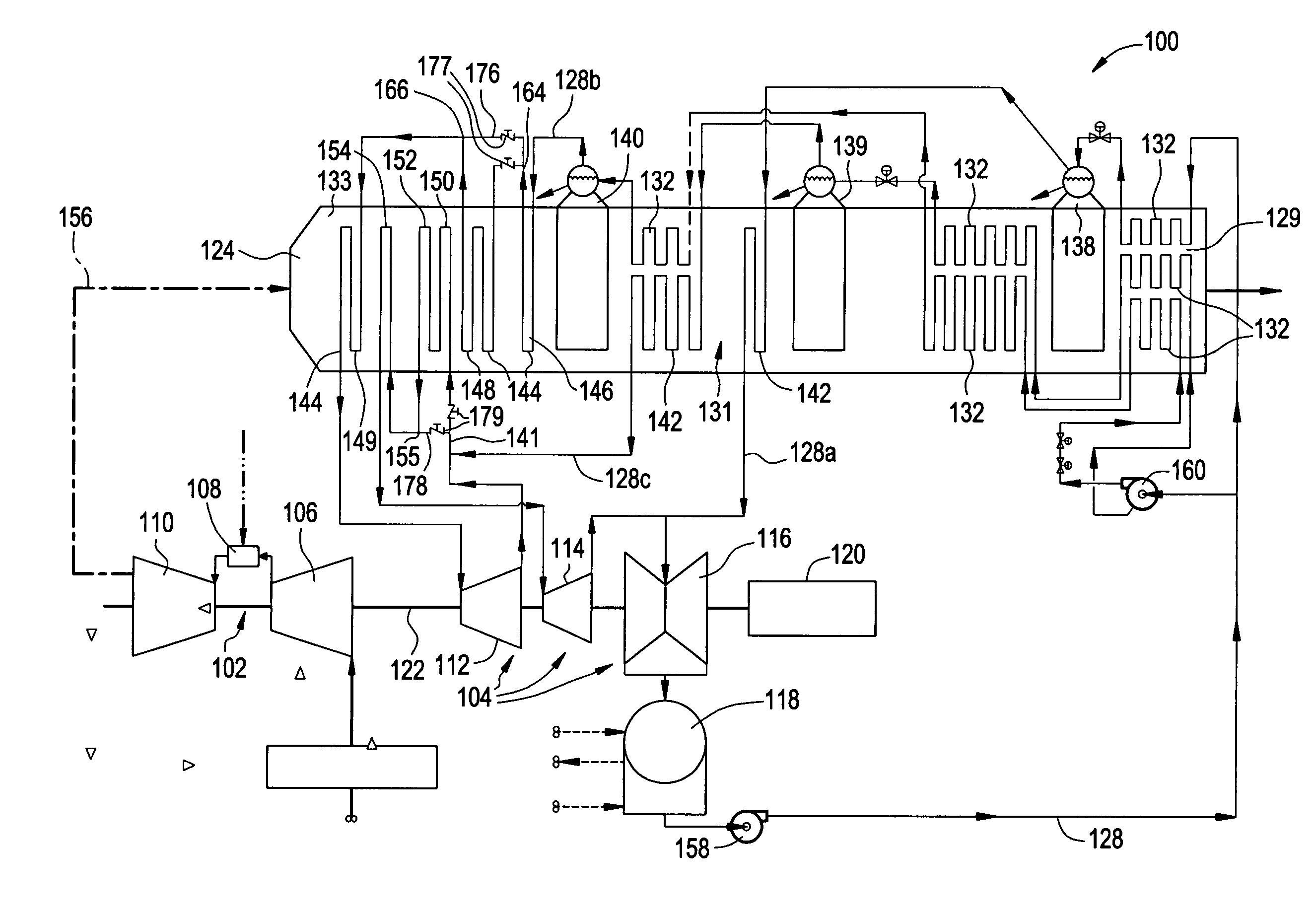
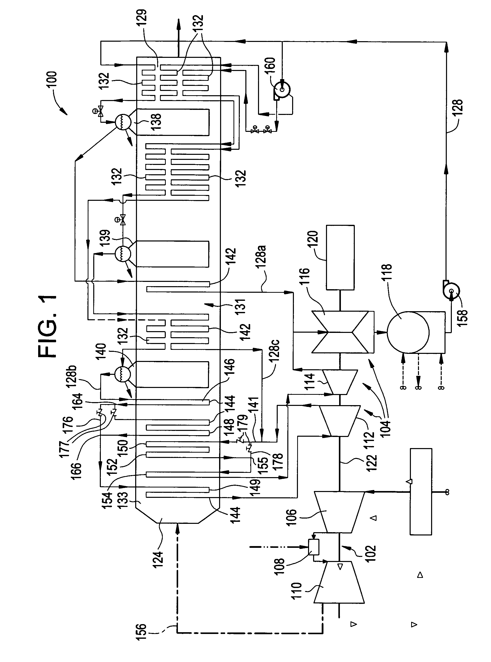
[0013]Referring to FIG. 1, a system 100 for controlling steam temperature is illustrated, and includes a gas turbine 102 and a steam turbine 104. The gas turbine 102 includes a compressor 106, a combustion area 108, and a turbine 110. The steam turbine 104 may include at least one high pressure section 112, at least one intermediate pressure section 114, and at least one low pressure section 116, wherein the at least one low pressure section 116 may exhaust into a condenser 118. The steam turbine 104 also drives a generator 120 that produces electrical power (or other load). The gas turbine 102 and steam turbine 104 are associated in tandem via a single shaft 122 that drives a single generator 120, though each may alternately drive separate loads.

[0014]The gas turbine 102 and steam turbine 104 are additionally associated with a multi-pressure heat recovery steam generator (HRSG) 124, which includes a high pressure (HP) region 133, an intermediate pressure (IP) region 131, and a low ...

second embodiment

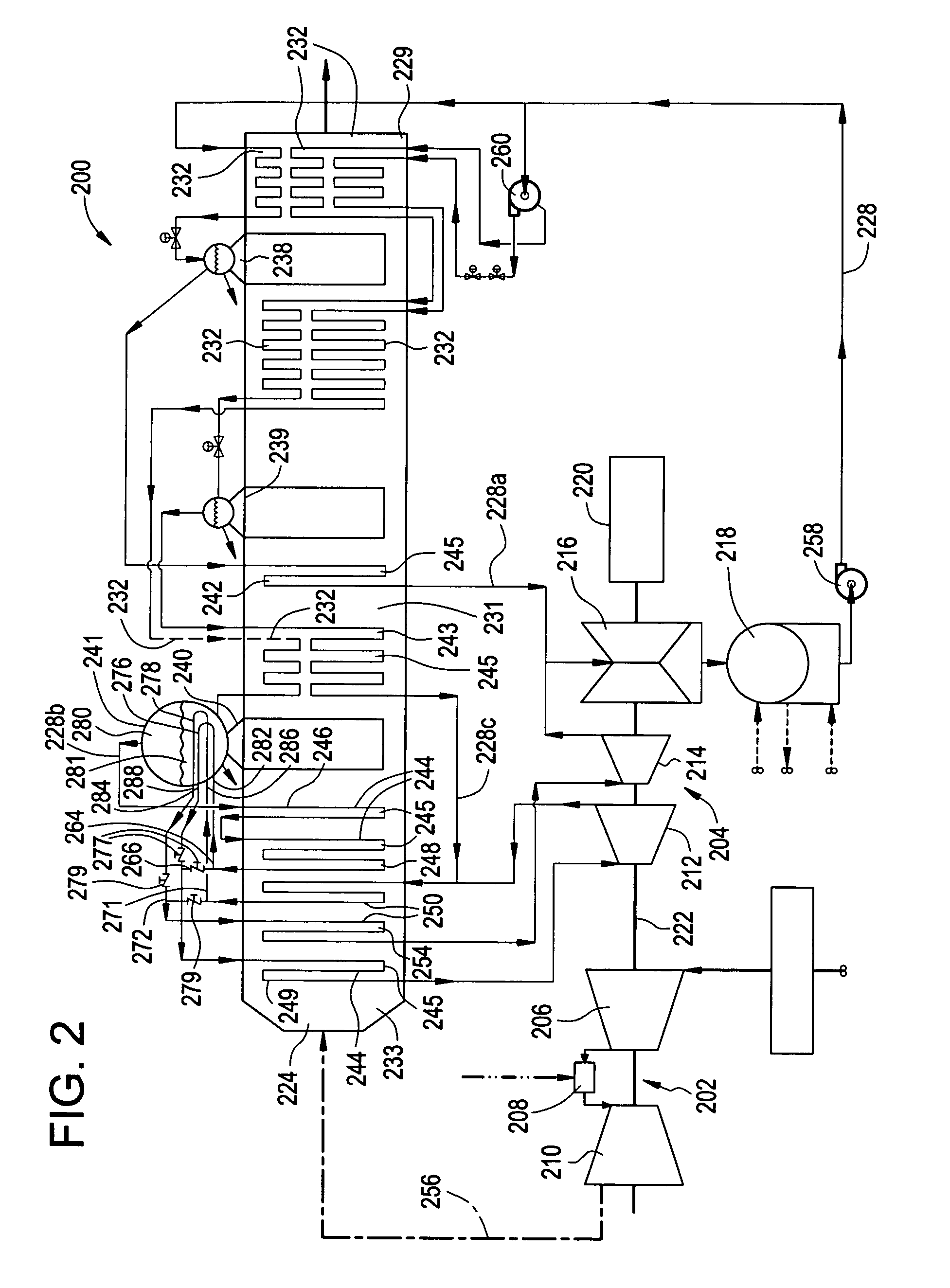
[0025]Referring to FIG. 2, a system 200 for controlling steam temperature is illustrated and includes a gas turbine 202 and a steam turbine 204. The gas turbine 202 includes a compressor 206, a combustion area 208, and a turbine 210. The steam turbine 204 may include at least one high pressure section 212, at least one intermediate pressure section 214, and at least one low pressure section 216, wherein the at least one low pressure section 216 may exhaust into a condenser 218. The steam turbine 204 also drives a generator 220 that produces electrical power (or other load). The gas turbine 202 and steam turbine 204 are associated in tandem via a single shaft 222 that drives a single generator 220, though each may alternately drive separate loads.

[0026]The gas turbine 202 and steam turbine 204 are additionally associated with a multi-pressure heat recovery steam generator (HRSG) 224, which includes a high pressure (HP) region 233, an intermediate pressure (IP) region 231, and a low p...


PUM


Abstract

A system for controlling steam temperature that includes steam circuit including a reheater circuit, at least one reheater dilution region, at least one reheater dilution conduit, and at least one reheater supply region disposed upstream of the at least one reheater dilution region, wherein the at least one reheater supply region and the at least one reheater dilution region are associated via the reheater circuit and the at least one reheater dilution conduit.

Description

FIELD OF THE INVENTION[0001]This disclosure relates generally to a system for controlling steam temperature, and more particularly to a system for controlling steam temperature within combined cycle power generation system.BACKGROUND OF THE INVENTION[0002]In general, a combined cycle power generation system includes a gas turbine, a steam turbine, a steam cycle, and a multiple pressure combined cycle heat recovery steam generator (HRSG). Steam supply to the steam turbine from the HRSG must be temperature controlled in order to keep the steam temperature from exceeding the rated temperature of the HRSG, interconnecting steam piping, and the steam turbine. One method for controlling and limiting steam temperature includes injection of a water spray into a conventional spray attemperator located upstream (in relation to steam flow) of the final reheater and superheater passes. The water source is typically a high pressure feedwater pump located upstream of at least one economizer dispo...

Claims


Application Information

Patent Timeline
IPC IPC(8): F02C6/00
CPCF01K23/106F02C6/18F22G5/16F22G5/18F22B35/007Y02E20/16
Inventor SMITH, RAUB WARFIELDGARDINER, BARRETT DAVIDGULEN, S. CAN
Owner GENERAL ELECTRIC CO
Why Eureka
Try Eureka