

Ice making machine
a technology of ice making machine and ice maker, which is applied in the direction of ice production, refrigeration machine, corrosion prevention, etc., can solve the problems of reducing the de-icing performance, and achieve the effect of efficient and stable de-icing operations
Active Publication Date: 2007-01-30
HOSHIZAKI ELECTRIC CO LTD
View PDF13 Cites 23 Cited by
- Summary
- Abstract
- Description
- Claims
- Application Information
AI Technical Summary
Benefits of technology
The invention is an ice making machine that uses a bypass line and valve device to supply hot gas from the compressor directly to the evaporator, without cooling the gas in the condenser. This results in efficient and stable de-icing operations regardless of external temperatures.
Problems solved by technology
However, when this refrigeration cycle is assessed with respect to its de-icing function, the following problem emerges.
However, when the outside air temperature is high, the hot gas from the compressor 1 is fed to the receiver 3 after being cooled in the condenser 2, thus causing a decrease in the de-icing performance.
Method used
View moreImage
Smart ImageViewing Examples

Examples
modification examples
[0060]Instead of the three-way valve 35 exemplified in the above Embodiments 6 and 7, for example, as shown in FIG. 10, two open / close valves 35A and 35B, which can be individually subjected to open / close control, may be respectively provided at a position on the auxiliary line 37 that branches from the refrigerant supply line 18A and connects to the accumulator 17, and a position on the CPR 23 side of the branching position.
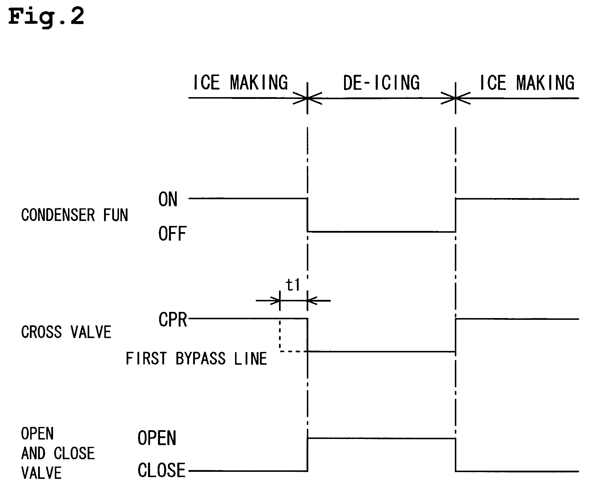
[0061]For Embodiments 6 and 7 also, a configuration may be adopted in which the condenser fan 12A continues to be driven during the de-icing operation.
Login to View More PUM
 Abstract
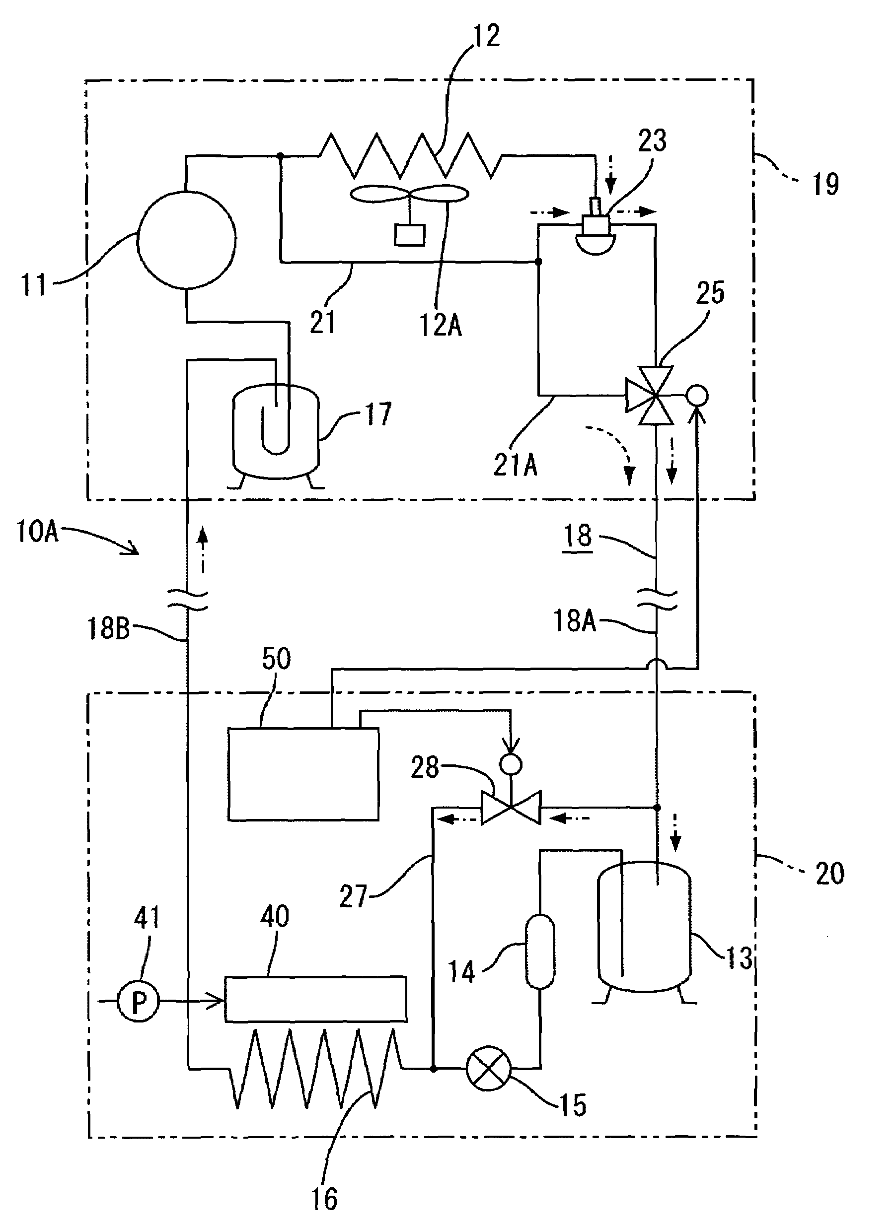
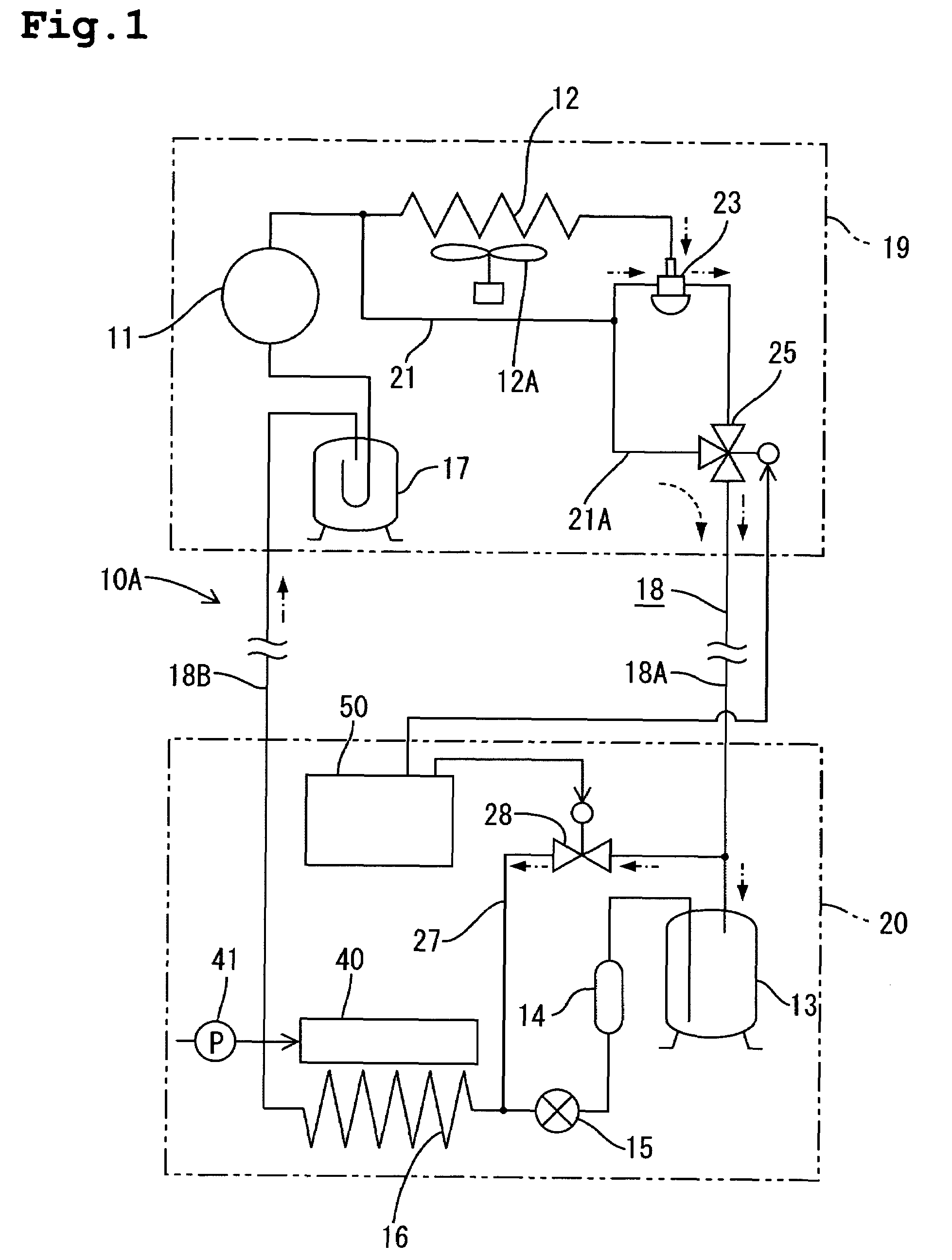
In external unit 19, three-way valve 25 provided downstream of CPR 23 enables a switching connection between CPR 23 and branch line 21A of first bypass line 21 with respect to liquid line 18 A. In internal unit 20, second bypass line 27 connects inlet side of receiver 13 and inlet side of evaporator 16, and open / close valve 28 is provided along second bypass line 27. At de-icing, three-way valve 25 switches to first bypass line 21 side and open / close valve 28 opens. There upon, hot gas from compressor 11 circulates from first bypass line 21 to liquid line 18A to enter evaporator 16 through second bypass line 27 while squeezing out liquid refrigerant. Evaporator 16 is heated by manifest heat of introduced hot gas, and when the internal pressure of vaporator 16 rises to a condensation temperature over 0° C., de-icing is performed efficiently by manifest heat plus latent heat.
Description
BACKGROUND OF THE INVENTION[0001]1. Field of the Invention[0002]The present invention relates to an ice making machine for making ice by means of a cooling function of an evaporator in a refrigeration circuit and accomplishing de-icing through a rise in temperature of the evaporator.[0003]2. Description of the Prior Art[0004]As one example of a conventional kind of ice making machine, the machine disclosed in Japanese Patent Laid-Open No. 2000-213841 is known. As shown in FIG. 11, in this machine a compressor 1, a condenser 2, a receiver 3, a dryer 4, an expansion valve 5, an evaporator 6, and an accumulator 7 (i.e., a liquid separator), are connected in a circulatory manner by refrigerant piping. Of these components the compressor 1, the condenser 2, and the accumulator 7, are disposed in an external unit, and the remaining components are disposed in an internal unit. On the outlet side of the condenser 2 is disposed a condensing pressure regulating valve 8 (CPR) to allow the flow ...
Claims
Login to View More Application Information
Patent Timeline
 Patent Type & AuthorityPatents(United States)
IPC IPC(8): F25C5/10
CPCF25B47/022F25C5/10F25B2400/0403F25C2600/04F25B2600/2507
InventorHIRANO, AKIHIKOSANUKI, MASAOTOYA, CHIYOSHIYOSHIDA, KAZUHIRO
OwnerHOSHIZAKI ELECTRIC CO LTD