System and method for testing fuel tank integrity

a fuel tank integrity and system technology, applied in the direction of fluid tightness measurement, instruments, machines/engines, etc., can solve the problems of unsatisfactory hydrocarbon pollution, many existing fuel tank integrity testing systems are expensive, inconsistent, cumbersome, etc., to prevent over-pressurization

Active Publication Date: 2007-01-30
OPUS INSPECTION
View PDF76 Cites 22 Cited by
  • Summary
  • Abstract
  • Description
  • Claims
  • Application Information

AI Technical Summary

Benefits of technology

[0021]According to an embodiment of the invention, the tank adaptor, outlet hose, and any pneumatic conduit or gasket materials may be comprised of material which may be pliable and impermeable to some or all gasoline constituents including, for instance, Methyl Tertiary Butyl Ether (MTBE), ethanol, and methanol. Material exhibiting these properties is known in the art. Furthermore, the tank adaptor, the outlet hose, and other elements within testing component may be fitted with quick disconnect couplers that facilitate easy and rapid connection and disconnection from the vehicle.Housing and Calibration Tank
[0060]Additionally, if at anytime during a procedure, the fuel tank pressure exceeds 28″ H2O gauge (or other predetermined emergency pressure level), as measured by the tank tester, the tank tester may open one or more valves and vent any remaining pressure in the fuel tank. The tank tester may also prevent pressurization of the fuel tank for any procedure until the problem has been corrected. In some embodiments, a pressure switch may enable the release of pressure from the testing component upon the detection of the predetermined emergency pressure level. The pressure switch may act as a back-up in the event that a pressure transducer (or other element of the testing component) fails. According to one embodiment, the pressure switch may be wired in series with one or more valves within the testing component and may manipulate said valves to prevent over-pressurization as a fail-safe measure.

Problems solved by technology

The loss of fuel from a vehicle fuel tank (and associated piping) through evaporation to the atmosphere may result in, among other things, undesirable hydrocarbon pollution.
Unfortunately, many existing fuel tank integrity testing systems can be expensive, cumbersome, and inconsistent.

Method used


Image

  • System and method for testing fuel tank integrity
  • System and method for testing fuel tank integrity
  • System and method for testing fuel tank integrity

Examples


Embodiment Construction

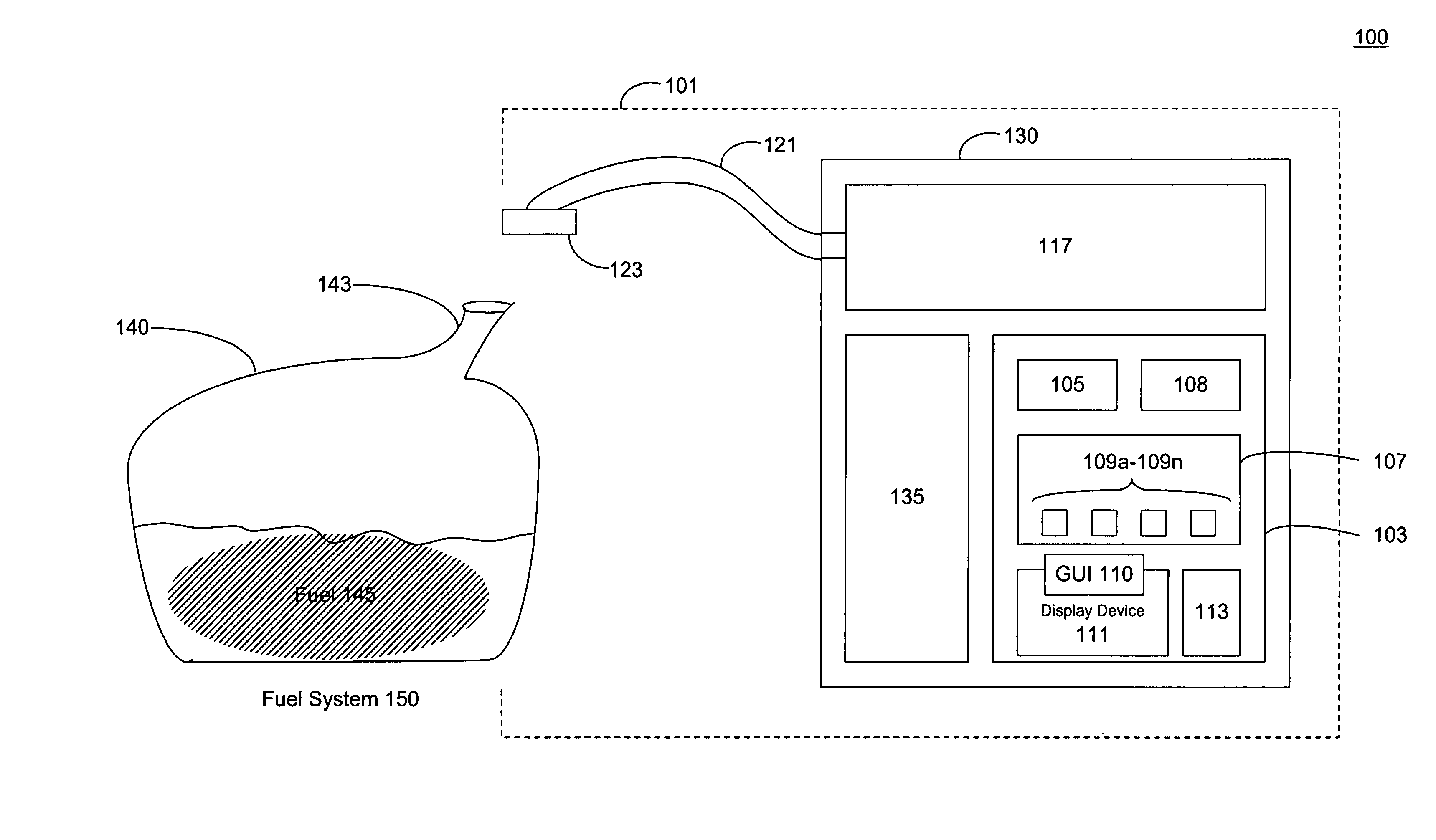
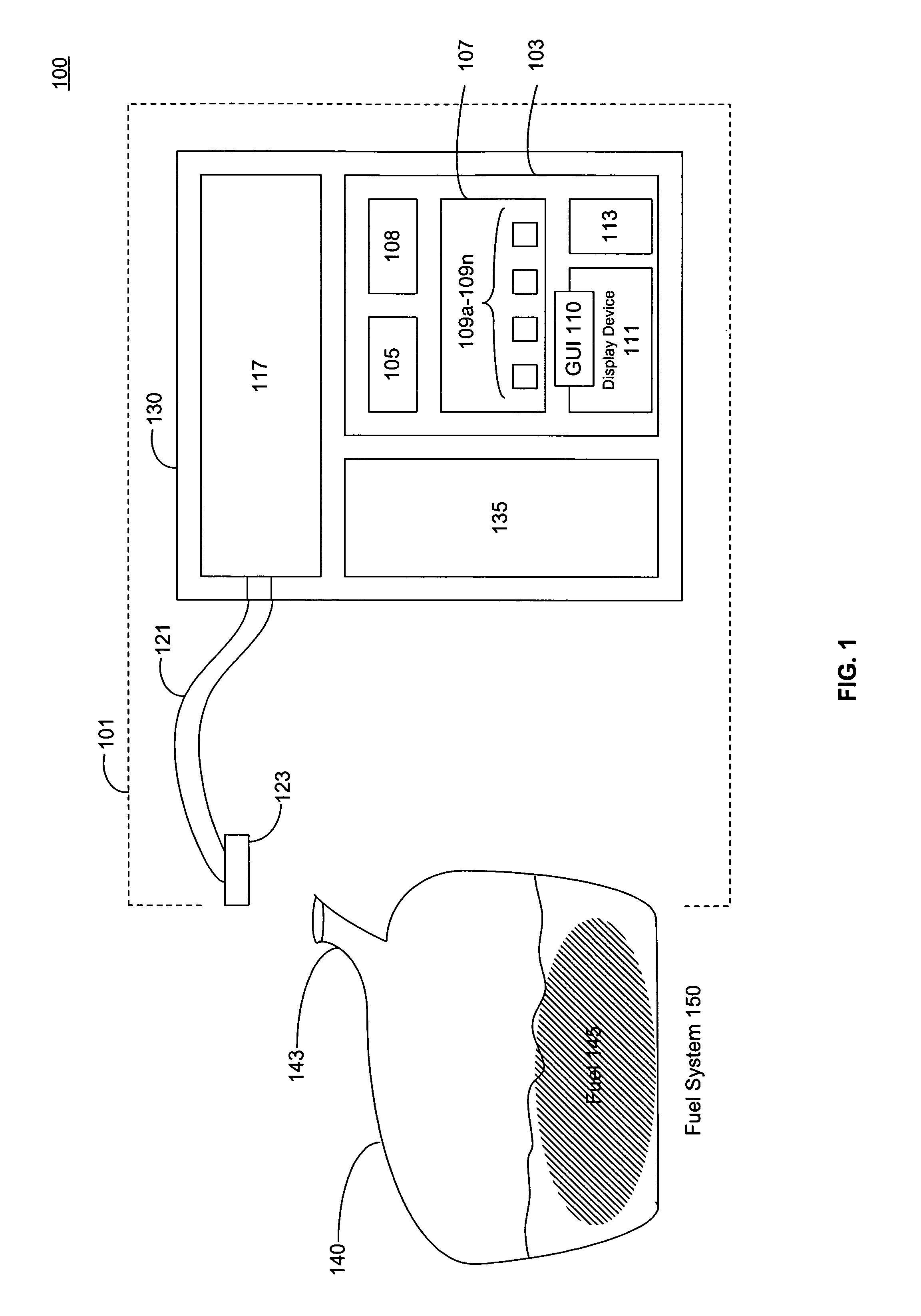
[0092]According to an embodiment illustrated in FIG. 1, a system 100 is provided for a tank tester 101. Tank tester 101 may be used to test the integrity of a fuel system 150, as described in greater detail below. Fuel system 150 may include a fuel tank 140, a fuel tank neck 143, fuel 145, and / or other elements. Fuel system 150 may by a fuel system for a car, motorcycle, light-duty truck, heavy-duty truck, or other motor vehicle. Tank tester 101 may include a computer-implemented component 103 (“computer component 103”), a testing component 117, a housing 130, a calibration tank 135, and / or other elements.
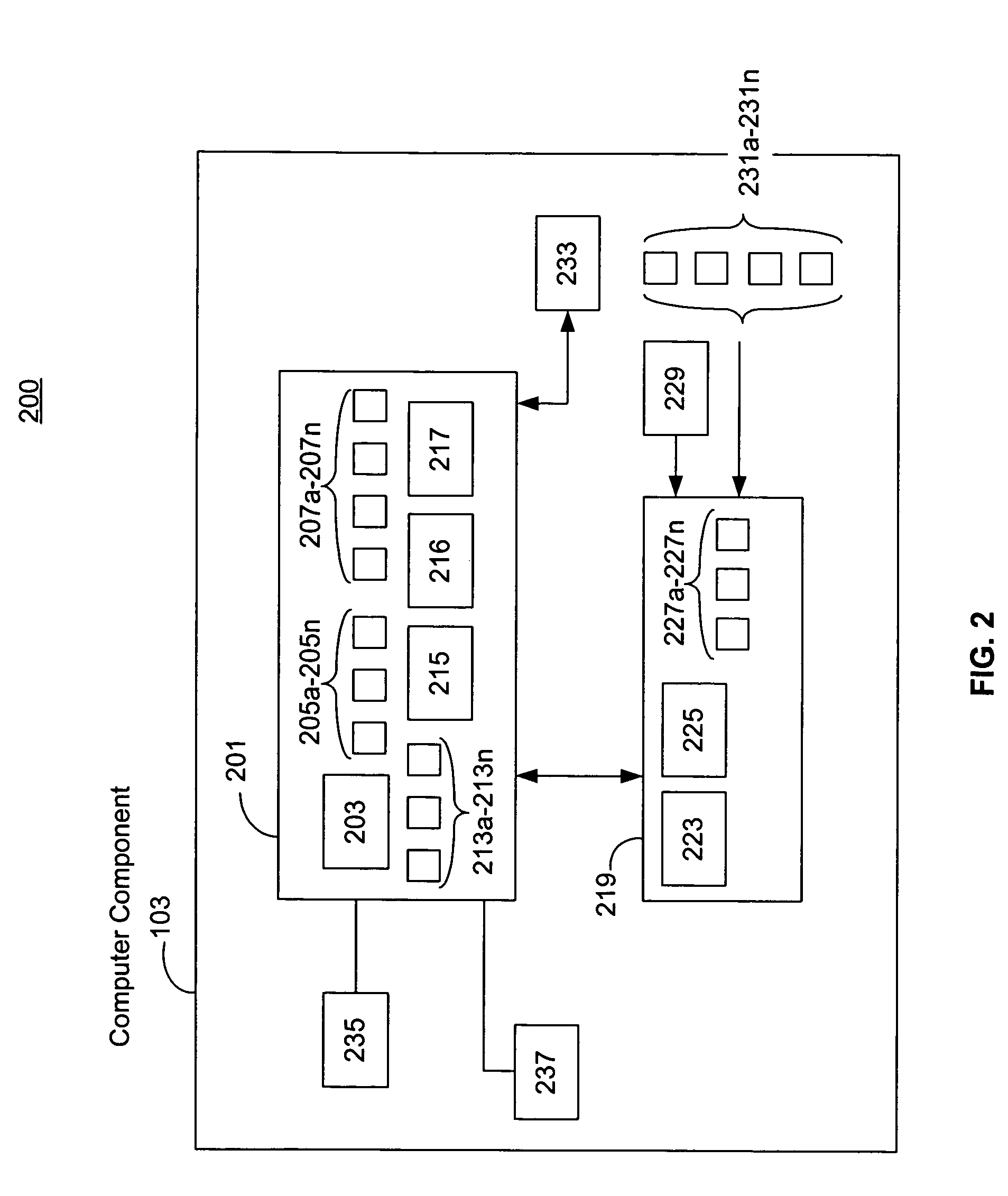
Computer Component

[0093]In one embodiment, computer component 103 may include various computer hardware and software elements such as, for example, a processor 105. Processor 105 may be or include, for instance, any of the Intel x86 PC / AT microprocessors or compatible processors such as those available from Cyrix or AMD.

[0094]Computer component 103 may include an operating applicat...


PUM


Abstract

The invention relates generally to a system and method for testing fuel evaporative systems, and more particularly to a stand-alone tank tester system (and method) for testing vehicle fuel tank integrity. Furthermore, a self-contained calibration tank with switchable leak sizes for calibrating the tank tester to multiple leak sizes is provided. Constant flow and vacuum methods for testing fuel tank integrity are also provided.

Description

CROSS-REFERENCE TO RELATED APPLICATIONS[0001]This application claims priority from U.S. Provisional Patent Application Ser. No. 60 / 514,745 filed Oct. 28, 2003, which is incorporated herein by reference in its entirety.FIELD OF THE INVENTION[0002]The invention relates generally to a system and method for testing fuel evaporative systems, and more particularly to a stand-alone tank tester system (and method) for testing vehicle fuel tank integrity.BACKGROUND OF THE INVENTION[0003]The loss of fuel from a vehicle fuel tank (and associated piping) through evaporation to the atmosphere may result in, among other things, undesirable hydrocarbon pollution.[0004]Accordingly, many systems and methods have been developed to test the tank integrity of vehicle fuel systems, and to identify vehicles that fail to comply with promulgated regulations and mandated guidelines (regardless of whether they are on the federal, state, or local level).[0005]Unfortunately, many existing fuel tank integrity t...

Claims


Application Information

Patent Timeline
Patent Type & Authority Patents(United States)
IPC IPC(8): G01M3/04G01M3/32
CPCG01M3/3236G01F17/00F02M25/08F02M37/20
Inventor HERZOG, MICHAELSMITH, GORDON ERNESTSULIK, CHARLES MICHAELPANDEY, ARUN R.SHISHKIN, VALERIY MAKSIMOVICHWEEDON, REX GRAHAMDAVIS, MARK
Owner OPUS INSPECTION
Why Eureka
Try Eureka