Multi-point grounding plate for fuel pump module

a fuel pump module and multi-point technology, applied in the direction of piston pumps, connection contact material, coupling device connections, etc., can solve the problems of multiple grounding wires, module, and less wiring efficiency

Active Publication Date: 2007-01-30
AISAN IND CO LTD
View PDF2 Cites 23 Cited by
  • Summary
  • Abstract
  • Description
  • Claims
  • Application Information

AI Technical Summary

Problems solved by technology

A major disadvantage of the current fuel pump module grounding method is that multiple grounding wires, each coming from a component of or around the fuel pump module, are required.
Because multiple wires are required, this technique is less efficient in terms of wiring and results in higher costs and longer assembly times. Additionally, with multiple wires, multiple points of wire disconnect may result, which may result in a higher probability that the parts of the fuel pump module will not be grounded at some point during their use.

Method used


Image

  • Multi-point grounding plate for fuel pump module
  • Multi-point grounding plate for fuel pump module
  • Multi-point grounding plate for fuel pump module

Examples


Embodiment Construction

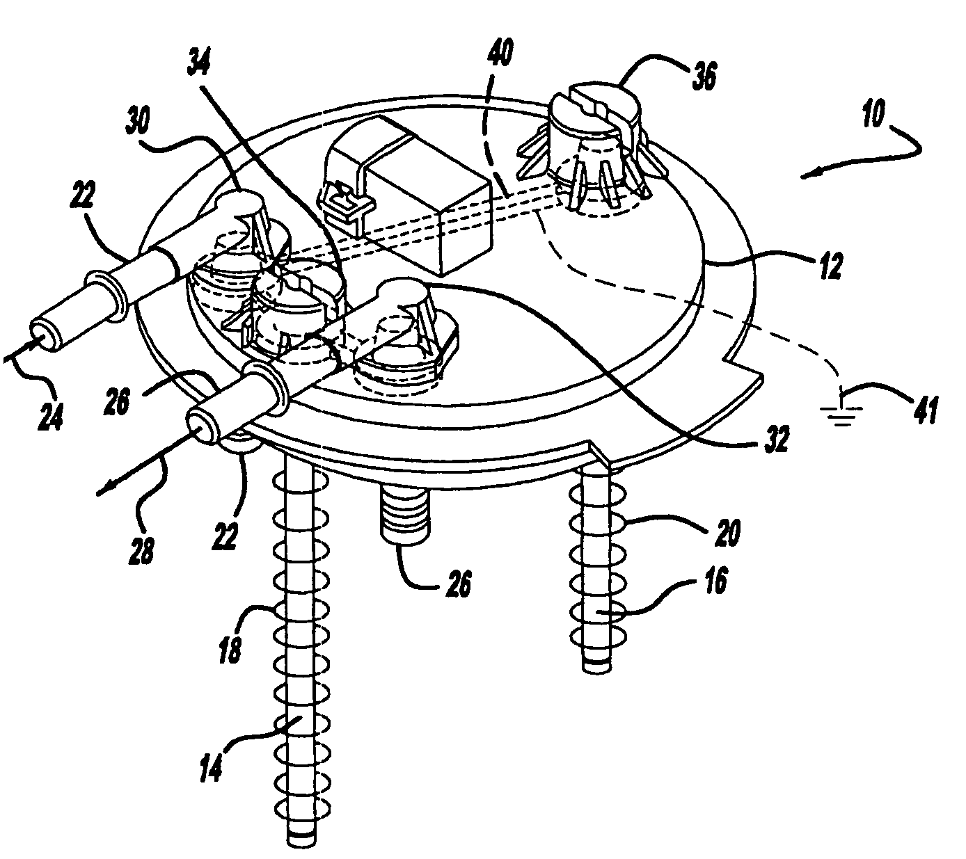
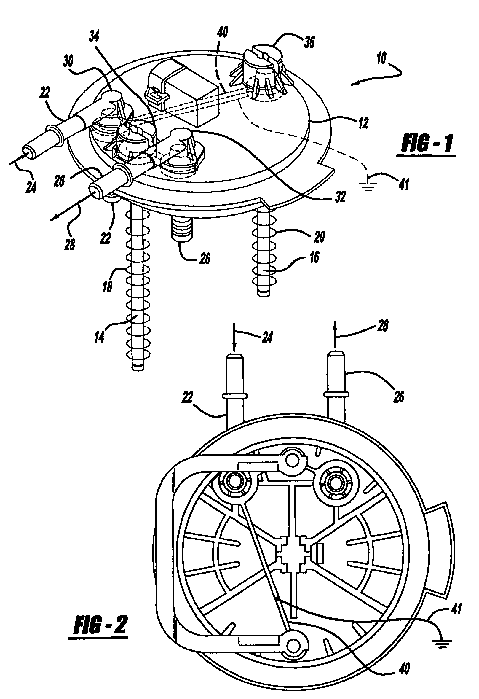
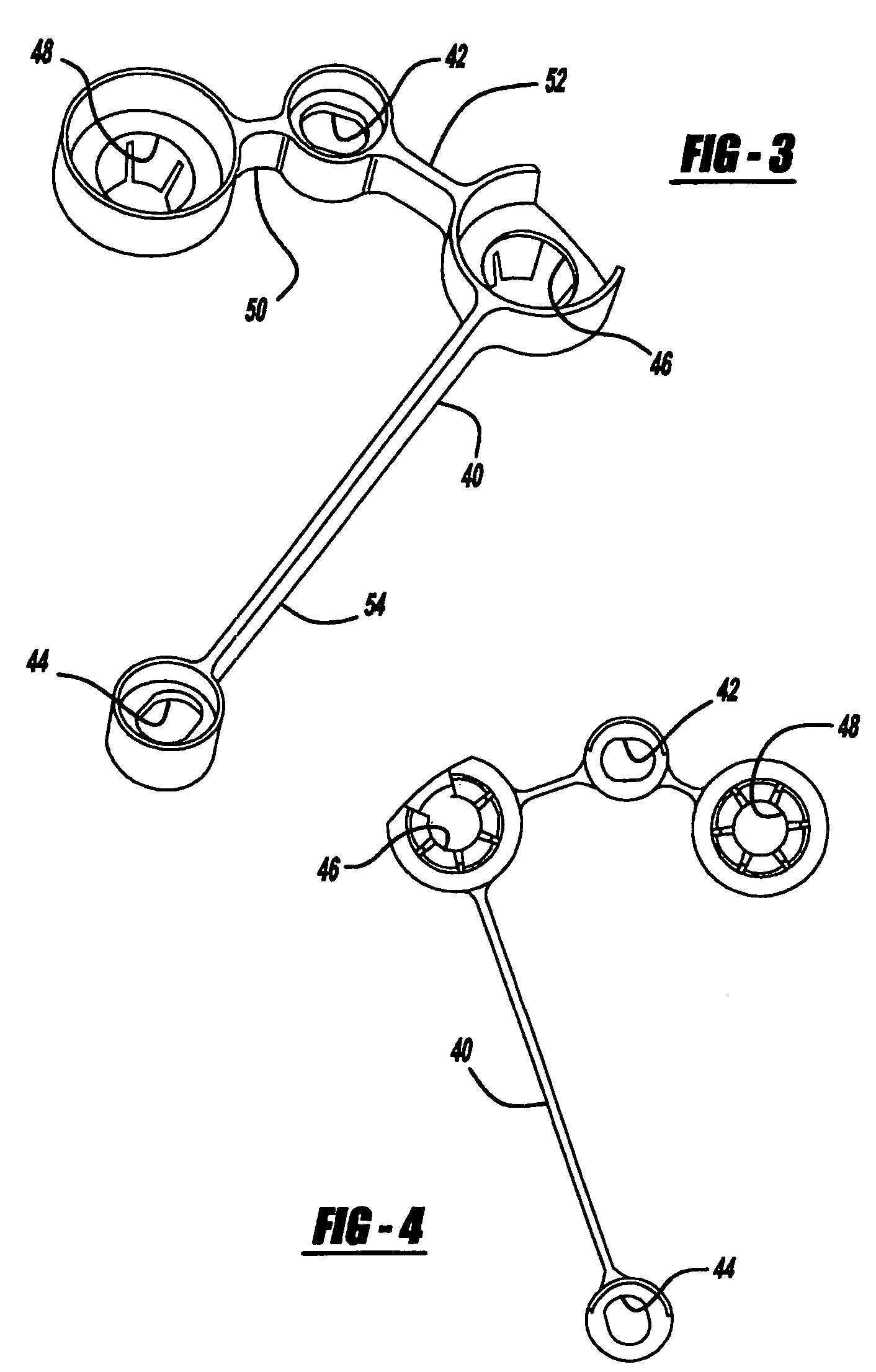
[0014]The following description of the preferred embodiments is merely exemplary in nature and is in no way intended to limit the invention, its application, or uses. Turning now to the Figures, the operative workings of the teachings of the present invention will be described. FIG. 5 is a side view of a fuel pump module 60 that depicts a multi-point grounding plate 40 on a bottom side of the fuel pump module flange 10 (FIG. 1) according to the teachings of the present invention. FIG. 5 also depicts a reservoir 62 that resides within a fuel tank 70, which is connected to the flange 64. The reservoir 62 is connected to the fuel pump module flange 10 by fuel lines 72, 74. Fuel line 72 is a return fuel line that delivers fuel from outside the fuel tank 70 to inside the fuel tank 70, while fuel line 74 is a fuel out line that delivers fuel from inside the fuel tank 70 to the vehicle engine (not shown). The struts or rods 14, 16 are typically metal that are each surrounded by a spring 18...


PUM


Abstract

A fuel pump module has a flange located proximate to the top of the fuel tank, a first strut rod, a second strut rod, a fuel inlet tube and a fuel outlet tube, each extending through the flange from a first side of the flange to a second side of the flange. A multi-point grounding plate is located on a side of the flange to contact and ground the strut rods, fuel tubes and adjacent parts. The grounding plate is generally disposed about a periphery of the flange, and a grounding wire, a first end of which is disposed on the grounding plate and a second end of which is disposed on a vehicle ground location, provides the necessary grounding path for the grounding plate.

Description

FIELD OF THE INVENTION[0001]The present invention relates to fuel pump modules and more specifically, to a multi-point grounding plate located on a fuel pump module flange for grounding parts of the fuel pump module.BACKGROUND OF THE INVENTION[0002]Parts that comprise automobile fuel pump modules are typically grounded in order to dissipate any static electricity buildup in the various parts of the fuel pump module that may contact liquid fuel or gaseous fuel fumes. Traditionally, fuel pump modules have various electrically conductive parts that each require a grounding wire to ensure that those parts are grounded since those parts might contact liquid fuel or any surrounding gaseous fumes of the liquid fuel. Typically, the top fuel pump module flange is mounted to the top of a fuel tank while the grounding wires are connected to an appropriate grounding point in order to fully connect conductive parts of the fuel pump module to ground.[0003]A major disadvantage of the current fuel ...

Claims


Application Information

Patent Timeline
Patent Type & Authority Patents(United States)
IPC IPC(8): F02M37/00H01R4/66F02M37/04B67D7/08
CPCF02M37/103B67D7/3236Y10T137/86027
Inventor POWELL, PATRICKMUKAIDANI, AKIYOSHI
Owner AISAN IND CO LTD
Why Eureka
Try Eureka