

Flow through pressure regulator with pinch valve
a pressure regulator and flow-through technology, applied in the direction of fluid pressure control, diaphragm valves, instruments, etc., can solve the problems of clogging of the regulator of this type, and achieve the effect of restricting the flow
- Summary
- Abstract
- Description
- Claims
- Application Information
AI Technical Summary
Benefits of technology
Problems solved by technology
Method used
Image

Examples
Embodiment Construction
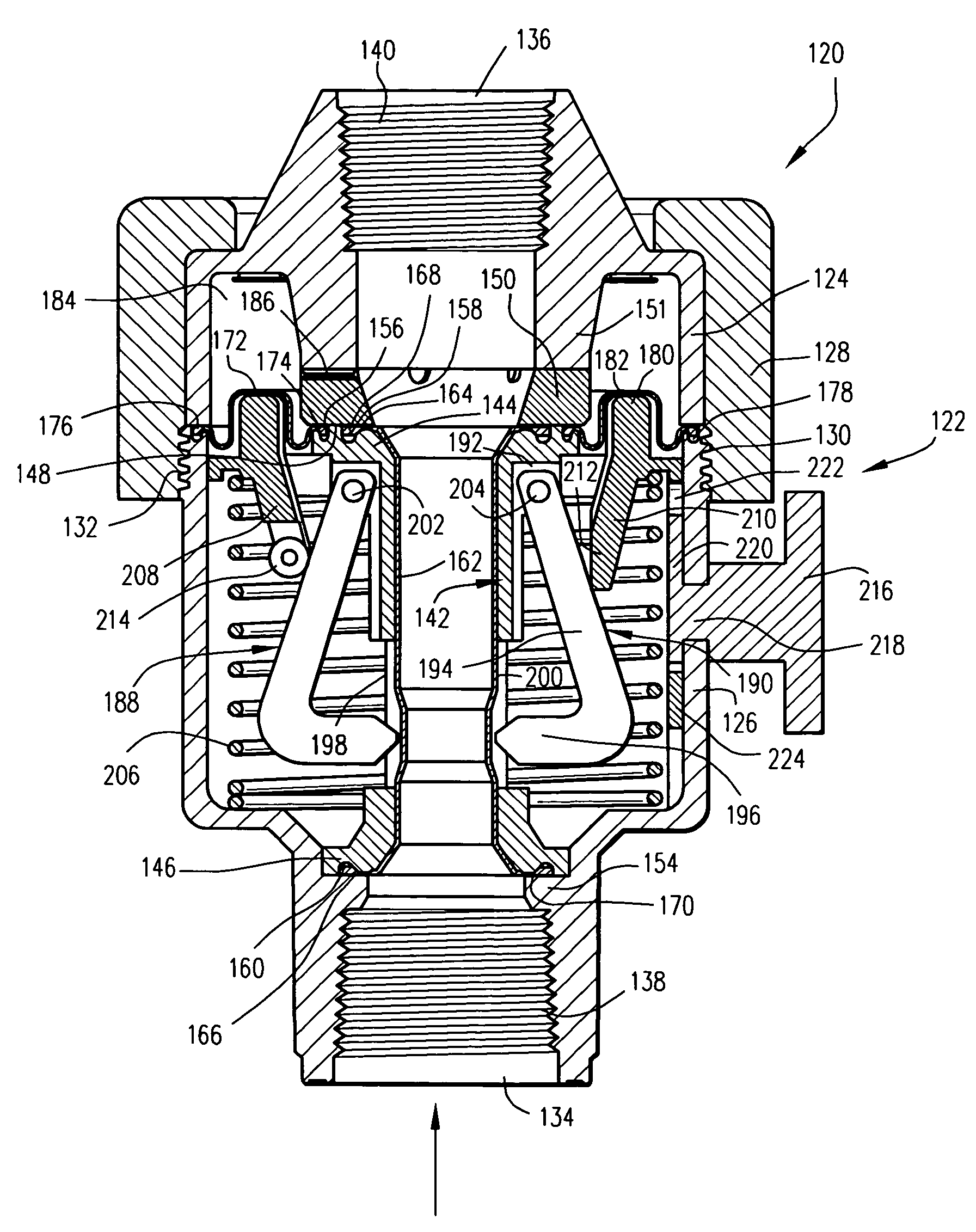
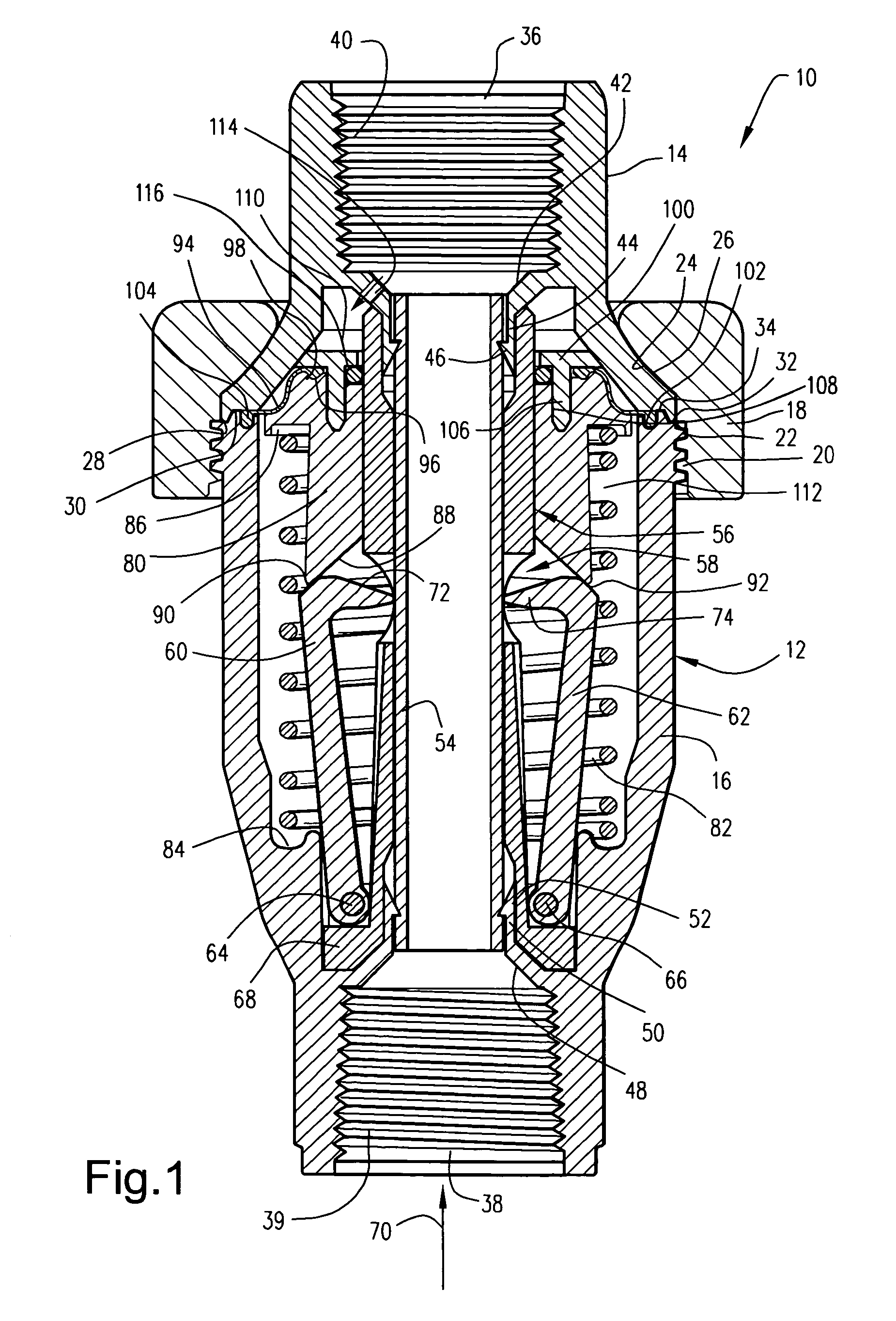
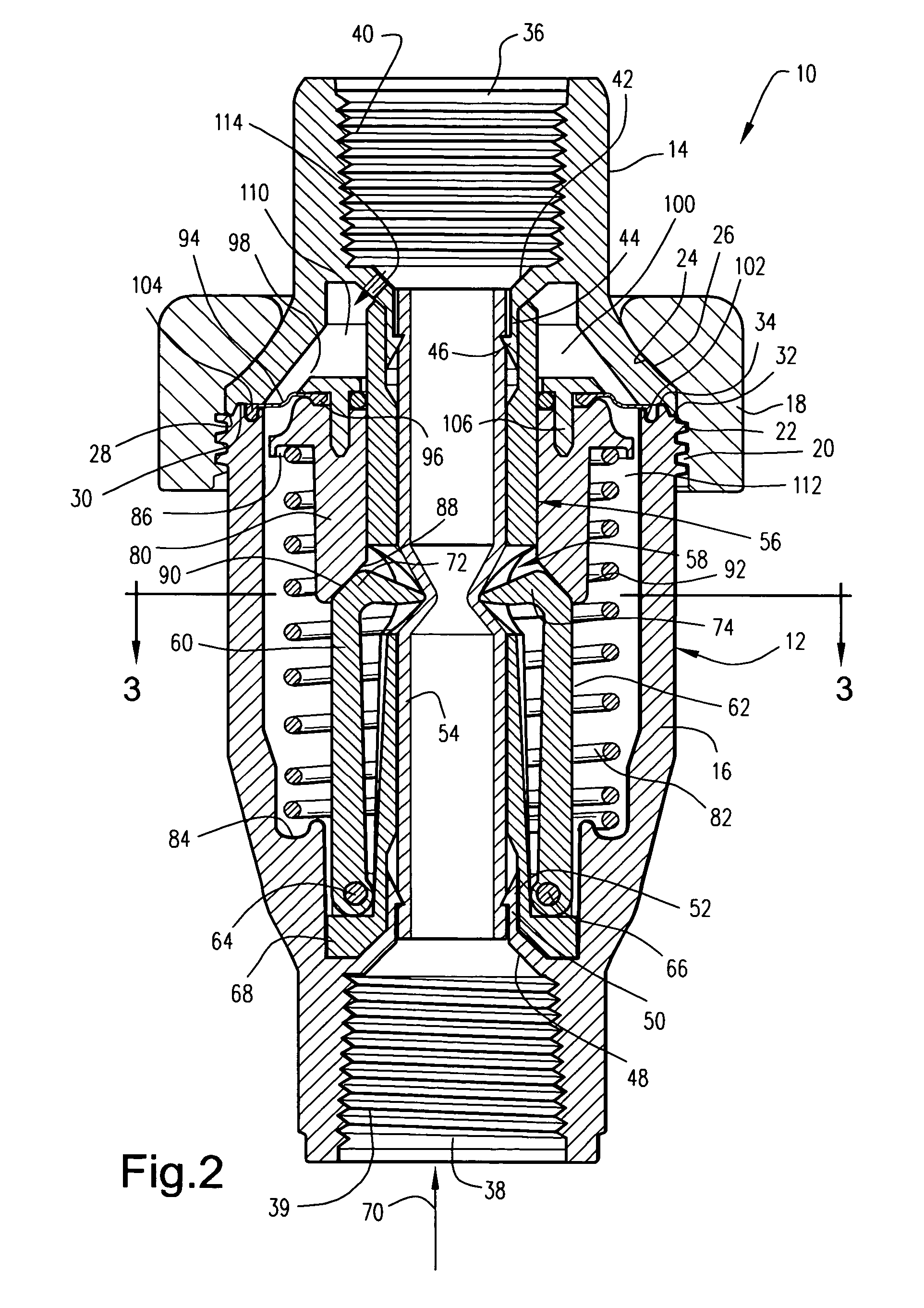
[0023]With reference to FIG. 1, a fluid pressure regulator 10 in accordance with a first exemplary embodiment of this invention includes a tubular housing 12 including a cap component 14 and a main body component 16 secured together by means of a donut-shaped clamp ring 18. More specifically, the clamp ring 18 may be telescoped over the cap component 14, enabling a threaded connection via the internal thread 20 on the clamp ring and the external thread 22 on the main body component 16 of the housing 12. As the clamp ring 18 is threaded onto the main body component 16, the tapered surface 24 on the inside of the clamp ring 18 engages similarly tapered surface 26 on the cap component 14 so that the cap component 14 is clamped to the main body component 16. Further in this regard, offset radial surfaces 28 and 30 on the cap component 14 engage offset radial surfaces 32 and 34, respectively, of the main body component 16 when the two sections are clamped together by the ring 18.
[0024]Th...
PUM
 Abstract
Description
Claims
Application Information