Electric power tool with locking mechanism

a technology of locking mechanism and electric power tool, which is applied in the direction of manufacturing tools, portable power-driven tools, portable drilling machines, etc., can solve the problems of less attractive cost-effectiveness, reduce ensure the optimal distribution of the load on the locking mechanism, and minimize the risk of failure of the locking mechanism

Inactive Publication Date: 2007-01-30
HILTI AG
View PDF8 Cites 4 Cited by
  • Summary
  • Abstract
  • Description
  • Claims
  • Application Information

AI Technical Summary

Benefits of technology

[0008]Since the process of clamping and unclamping is already controlled on the clamping lever itself, a structurally simple and effective solution of the objective is possible. In particular, the user of the electric power tool will immediately notice that the clamping device is in the locked state. As a result of the mechanical coupling of the clamping lever with the safety element, by means of the locking mechanism, a reliable locking in the clamped state in the safety position is ensured. Other mechanical solutions that act later in the effect chain of the clamping device are characterized by more complex engineering and consequently are less attractive in terms of their cost-effectiveness. In comparison to an electronic solution, the important advantage exists that the function is ensured, even in case of a power failure, in addition to which the electronic solutions are fundamentally less economical and less sturdy.
[0010]In a preferred embodiment, the recess is situated on an external pivoting range of the clamping lever so as to have the greatest possible distance from a pivoting axis of the clamping lever. If forces are exerted on the locked clamping lever from the outside, then an optimal distribution of the load on the locking mechanism is ensured. The closer the locking mechanism is to the place where the force is exerted by the clamping lever, the less the load on the locking mechanism in case of improper operation. This minimizes the risk of failure of the locking mechanism.

Problems solved by technology

Other mechanical solutions that act later in the effect chain of the clamping device are characterized by more complex engineering and consequently are less attractive in terms of their cost-effectiveness.

Method used


Image

  • Electric power tool with locking mechanism
  • Electric power tool with locking mechanism
  • Electric power tool with locking mechanism

Examples


Embodiment Construction

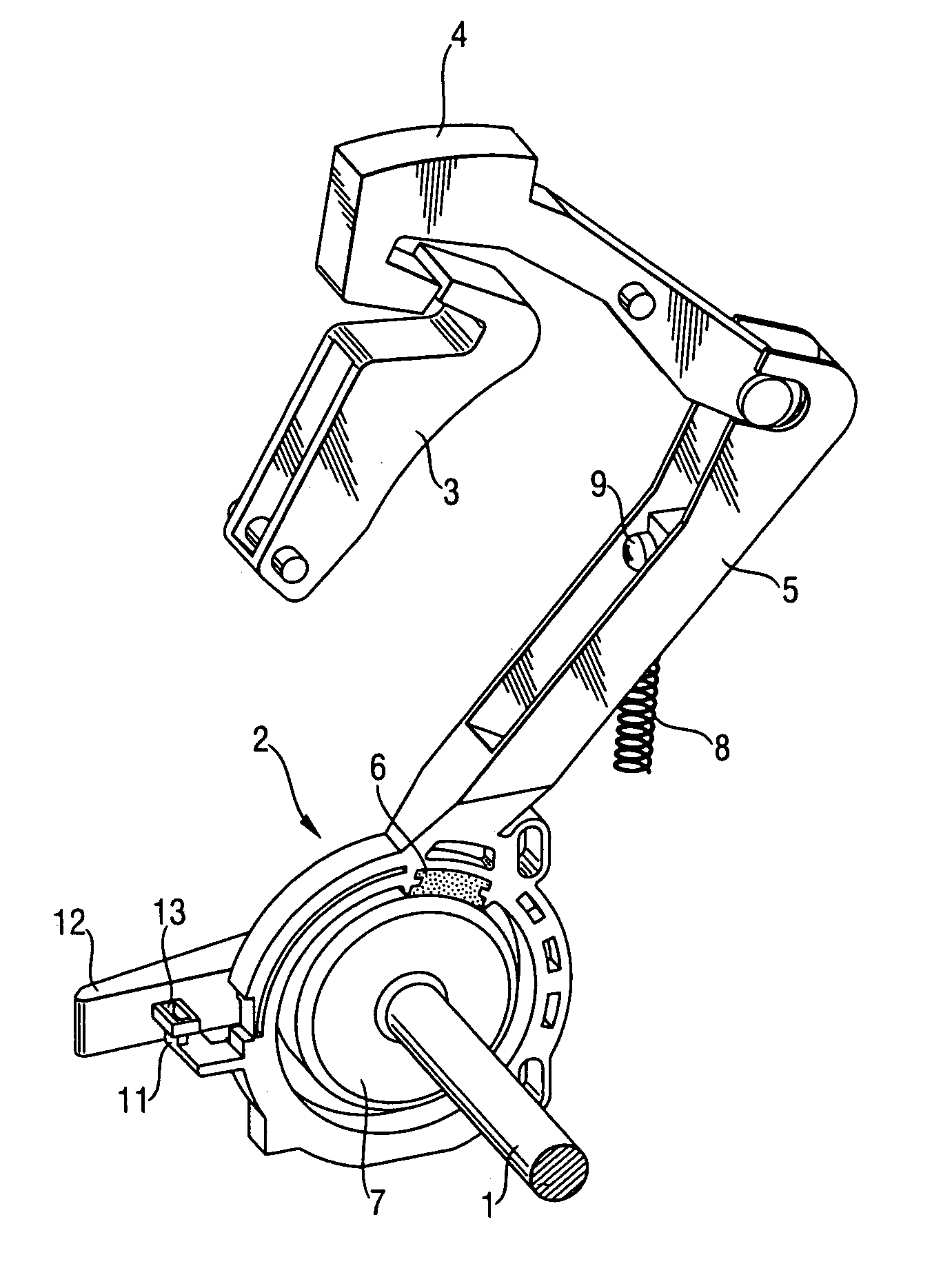
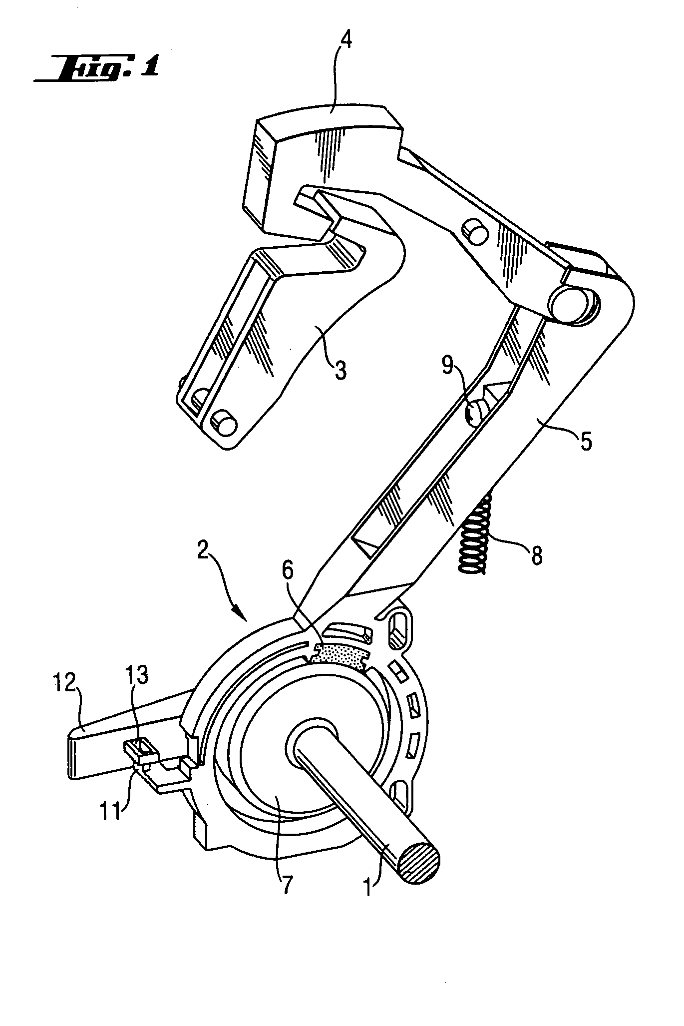
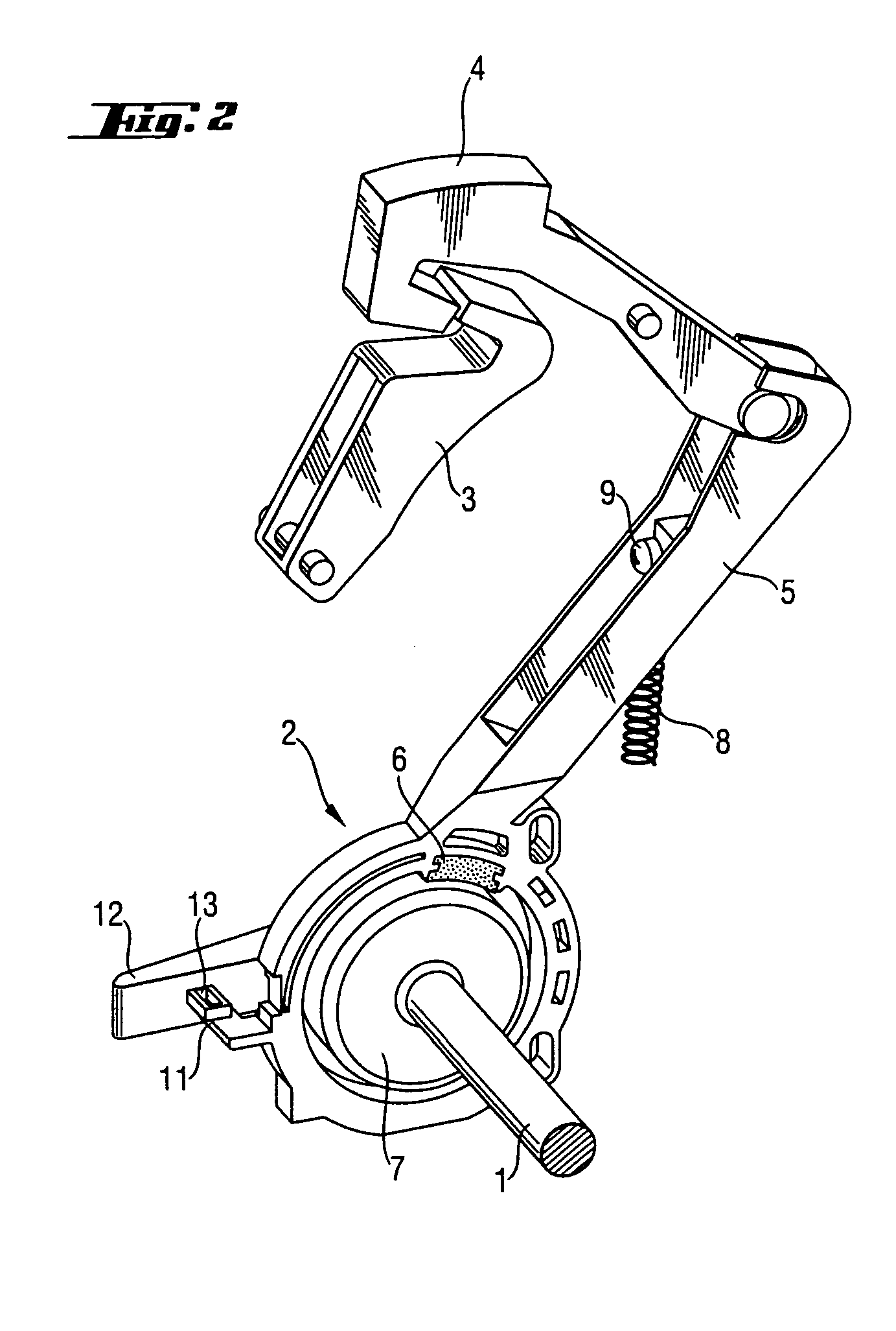
[0017]FIGS. 1 through 4 show an electric power tool according to the invention having a circular tool T that is driven by a motor M, whereby the tool can be clamped to a motor-driven shaft 1 by means of a clamping device C. In order to brake the tool, the electric power tool has a mechanical braking device 2 that is mechanically connected to a safety element 4 by an actuation part 5. The safety element 4 has a safety position in which it is not possible to turn on the motor M and in which the braking device 2 is activated, as is shown especially in FIG. 1. In a release position, the motor M can be turned on by means of a switching element 3 and the braking device is released, which is especially clear from FIG. 2.

[0018]The braking device 2 has a brake part 6 attached to the actuation part 5 and a brake drum 7 attached to the shaft 1. When the safety element 4 is in the safety position, then the actuation part 5 is pushed essentially radially with respect to the shaft 1 by means of a...


PUM

PropertyMeasurementUnit
rotational speedaaaaaaaaaa
mechanicalaaaaaaaaaa
areaaaaaaaaaaa

Abstract

An electric power tool has a motor-driven circular tool that can be clamped by means of a clamping device. A mechanical braking device (2) serves to brake the tool. A safety element (4) prevents improper handling of the electric power tool. In a safety position, the safety element (4) prevents the motor from being turned on and activates the braking device (2). In a release position, the safety element (4) allows the motor to be turned on and the braking device (12) is released. An additional locking mechanism prevents that a clamping lever, needed to actuate the clamping device, can be actuated in the clamped state in the safety position. In the release position of the safety element, the locking mechanism is unlocked.

Description

RELATED APPLICATION[0001]This is a continuation-in-part of patent application Ser. No. 09 / 931,135 filed Aug. 16, 2001 now abandoned.BACKGROUND OF THE INVENTION[0002]The invention relates to an electric power tool, especially to a hand-held circular saw, routing machine and the like, having a circular tool that is motor-driven by means of a shaft, whereby the tool can be clamped to the shaft by means of a clamping device that can be actuated by a clamping lever; having a mechanical braking device that, when activated, brakes the tool; a switching element to turn the motor ON and OFF; and a safety element which, when in a safety position, prevents the motor from being turned on and activates the braking device and which, when in a release position, allows the motor to be turned on and releases the braking device, whereby the braking device is mechanically connected to the safety element.[0003]Electric power tools, especially hand-held circular saws of the type described above, use saf...

Claims


Application Information

Patent Timeline
Patent Type & Authority Patents(United States)
IPC IPC(8): B23Q3/12B25F5/00B27B5/38
CPCB27B5/38B25F5/001Y10T83/7693Y10T83/081Y10T83/9464Y10T83/7747
Inventor HARTMANN, MARKUS
Owner HILTI AG
Why Eureka
Try Eureka