Paper transporting apparatus

a technology of paper transporting apparatus and paper, which is applied in the directions of transportation and packaging, electrographic processes, instruments, etc., can solve the problems of complex operation, deformation of the upper cover, and the loss of the paper transporting apparatus

Active Publication Date: 2007-01-30
OKI ELECTRIC IND CO LTD
View PDF6 Cites 24 Cited by
  • Summary
  • Abstract
  • Description
  • Claims
  • Application Information

AI Technical Summary

Benefits of technology

[0005]An object of the invention is to provide a paper transportation apparatus in which when paper is jammed in a paper-transporting mechanism used for double-sided printing, the jammed paper can be removed without difficulty.
[0006]Another object of the invention is to provide a paper-transporting apparatus that minimizes deformation of an upper cover of a paper-transporting mechanism resulting from urging forces of springs that urge pressure rollers, thereby allowing stable paper transportation.

Problems solved by technology

When a paper jam occurs, the user draws out the unit assembly from the main body of the image-recording apparatus.
The conventional paper-transporting apparatus for double-sided printing suffers from the following problem.
This operation is complex.
The upper cover may be subjected to deformation such as warping or bulge in its middle portion due to the urging force of springs that urge the pressure rollers against the drive rollers.
Deformation of the upper cover causes the print paper to become skewed and jammed.
Thus, the drive rollers and driven rollers will not apply uniformly distributed pressure to the paper passing between the drive rollers and driven rollers.
A non-uniform application of pressure often causes the paper to become skewed or jammed.

Method used


Image

  • Paper transporting apparatus
  • Paper transporting apparatus
  • Paper transporting apparatus

Examples


first embodiment

{Construction}

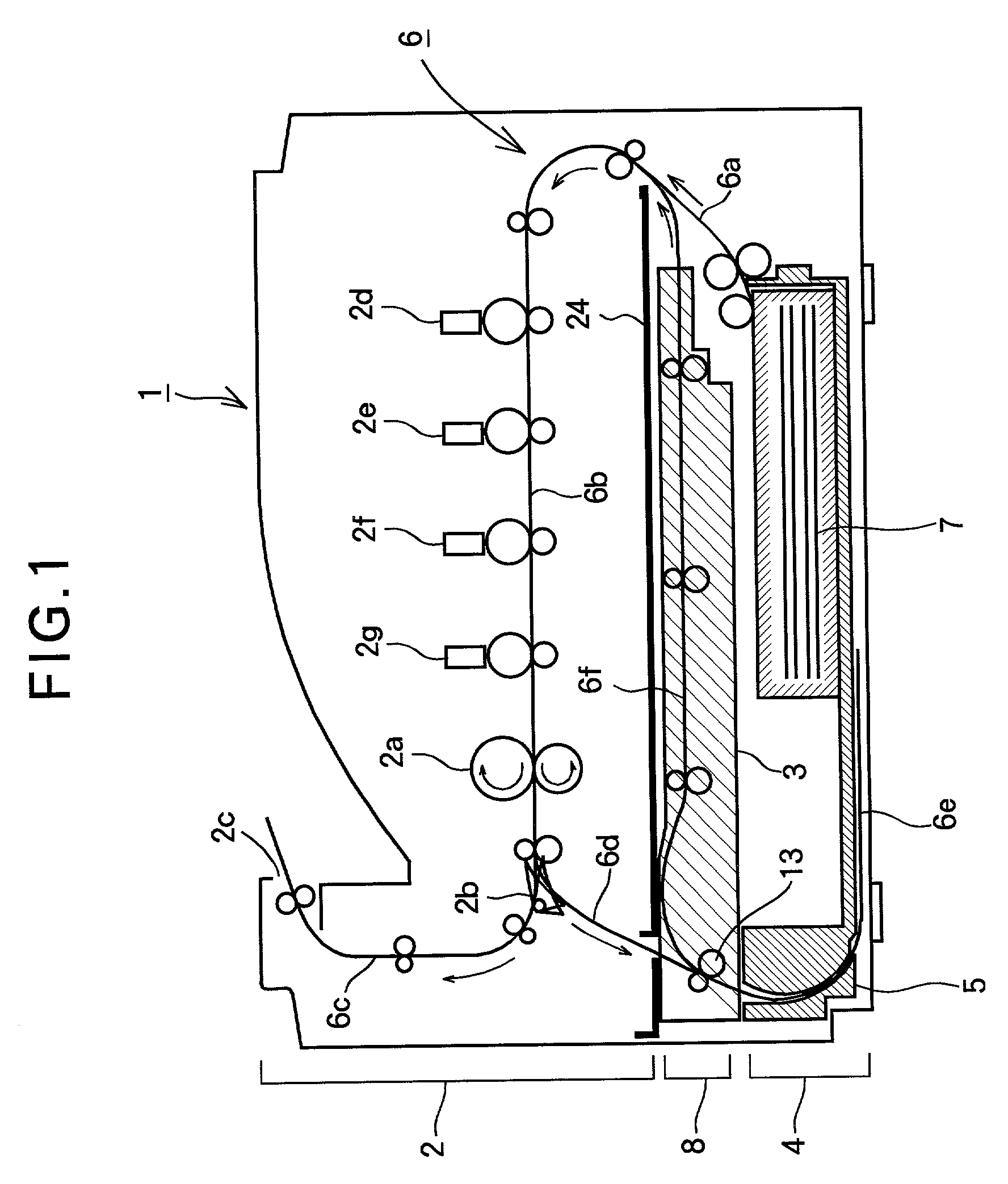
[0031]FIG. 1 illustrates a general configuration of an image-recording apparatus having a paper-transporting apparatus according to a first embodiment of the invention.

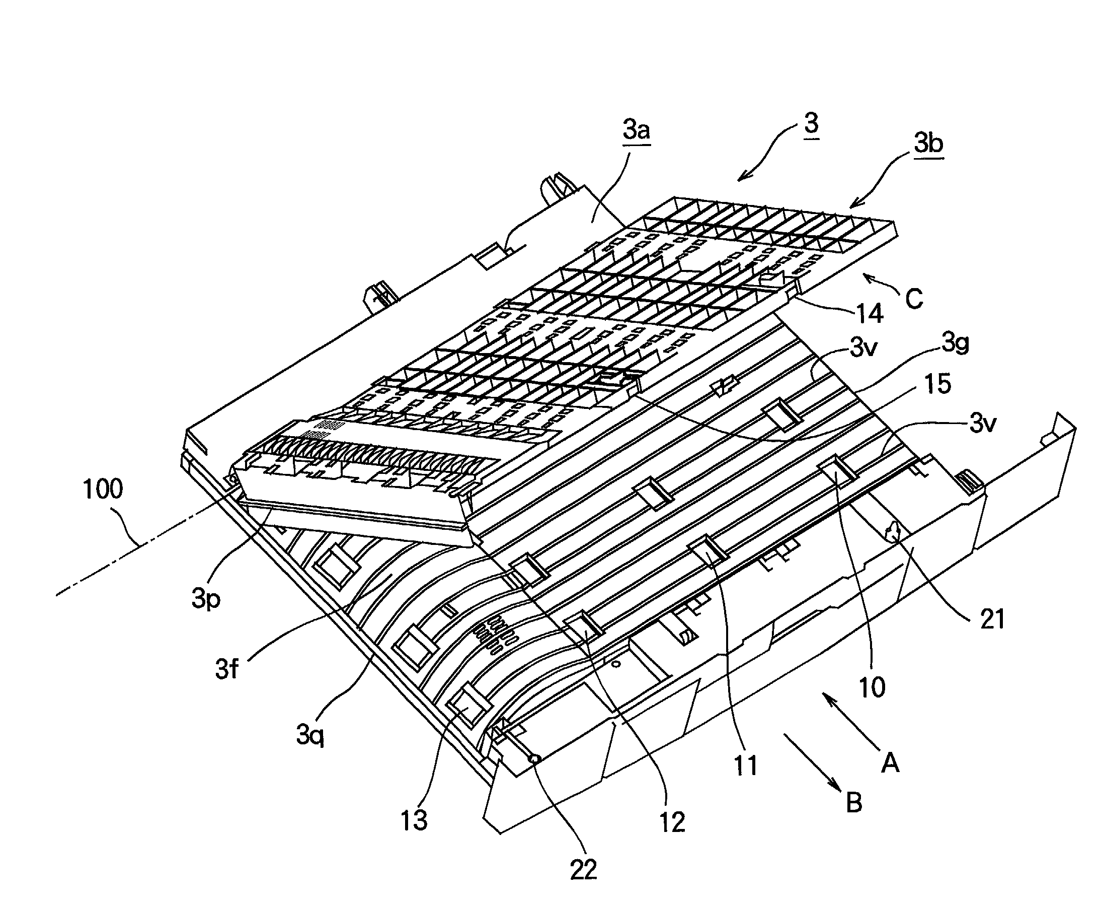
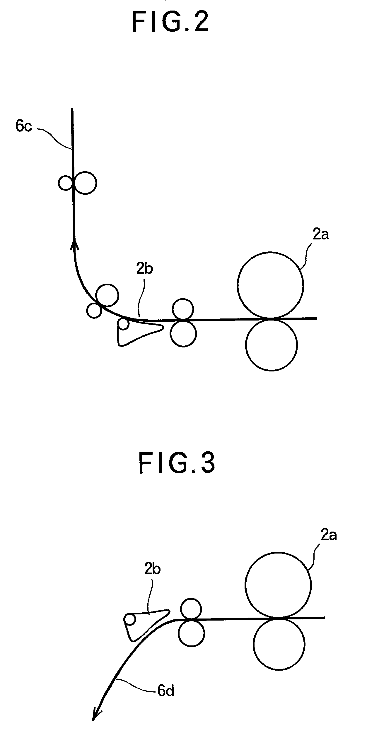
[0032]Referring to FIG. 1, a cassette-receiving section 4 receives a paper cassette 5 that holds a stack of recording paper 7 therein. A paper-transporting apparatus 8 has a guide means that supports a paper-transporting unit 3 thereon in such a way that the paper-transporting unit 3 can be loaded into and unloaded from the image-recording apparatus 1. The paper-transporting unit 3 transports the recording paper 7 when printing is performed on the both sides of the recording paper. A recording section 2 includes four print engines 2d–2g that transfer toner images of corresponding colors sequentially onto the recording paper 7 as the recording paper 7 passes through the path 6b. A fixing section 2a is located shortly after the print engine 2g and fuses the toner images transferred on the recording paper 7...


PUM


Abstract

A paper-transporting apparatus is used for transporting recording paper. A paper-transporting device is movable between a loading position where the paper-transporting unit has been completely attached into a chassis and an unloading position where the paper-transporting unit has been completely drawn out of the chassis. A guide member that supports the paper-transporting device and guides the paper-transporting device between the loading position and the unloading position. The paper-transporting device has a cover and a frame that cooperate with each other to form a paper path in which a recording paper is advanced. When the paper-transporting device is at the loading position, a positioning device holds the cover at a certain position with respect to the frame. When the paper-transporting device is at the unloading position, the positioning device does not hold the cover at the certain position with respect to the frame.

Description

FIELD OF THE INVENTION[0001]The present invention relates to a paper-transporting apparatus for use in an image-recording apparatus, and more particularly to a paper-transporting apparatus for use in an image-recording apparatus capable of printing on both sides of a sheet of paper.DESCRIPTION OF THE RELATED ART[0002]A conventional paper-transporting apparatus for use in an image-recording apparatus includes a unit assembly with a paper-transporting mechanism suitable for printing on both sides of a sheet of print paper. The unit includes a frame that supports a drive roller, an upper cover that supports a driven roller, and other associated structural members that fix the upper cover at a predetermined position. The upper cover is provided on a side from which a user can access the paper-transporting mechanism. When a paper jam occurs, the user draws out the unit assembly from the main body of the image-recording apparatus. Then, the user unlocks firmly fixed members manually befor...

Claims


Application Information

Patent Timeline
Patent Type & Authority Patents(United States)
IPC IPC(8): B65H5/02G03G15/00B65H5/06B65H5/38B65H85/00H04N1/00
CPCH04N1/00567H04N1/00538
Inventor ISAKA, NORIHISAKATO, YASUYUKI
Owner OKI ELECTRIC IND CO LTD
Why Eureka
Try Eureka