Sealing device

a technology of sealing device and sealing chamber, which is applied in the field of sealing device, can solve the problems of pain, paralysis of muscle groups, and disturbance of sensation, and approximately 1% of procedures are associated with complications

Inactive Publication Date: 2007-01-30
KENSEY NASH CORP
View PDF37 Cites 96 Cited by
  • Summary
  • Abstract
  • Description
  • Claims
  • Application Information

AI Technical Summary

Benefits of technology

[0009]In an embodiment of the occluder in accordance with the invention, the sealing element—also called a plug—is designed in such a way that it unfolds in the blood vessel after passing through the sheath and can, therefore, no longer come out again. In such an embodiment, the plug is preferably essentially circular, heart-shaped or oval. The fixation attachment or the fixation thread remains on the outside of the blood vessel in such an embodiment and is held in place by the skin. The fixation attachment is positioned through the site of the puncture. During removal of the sheath, the plug which has been inserted into the blood vessel is carefully pulled back toward the puncture site. The fixation attachment is preferably positioned essentially in the center of the flat sheet or in the vicinity thereof. The plug completely seals off the puncture site after

Problems solved by technology

The procedure is associated with quite a few complications which are inherent in the technique which is currently used.
Neighboring nerves can also become pinched if bleeding is sufficiently pr

Method used


Image

  • Sealing device
  • Sealing device
  • Sealing device

Examples


Embodiment Construction

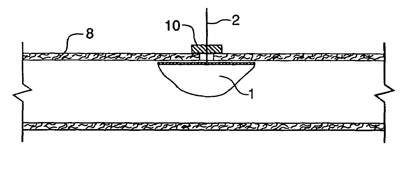
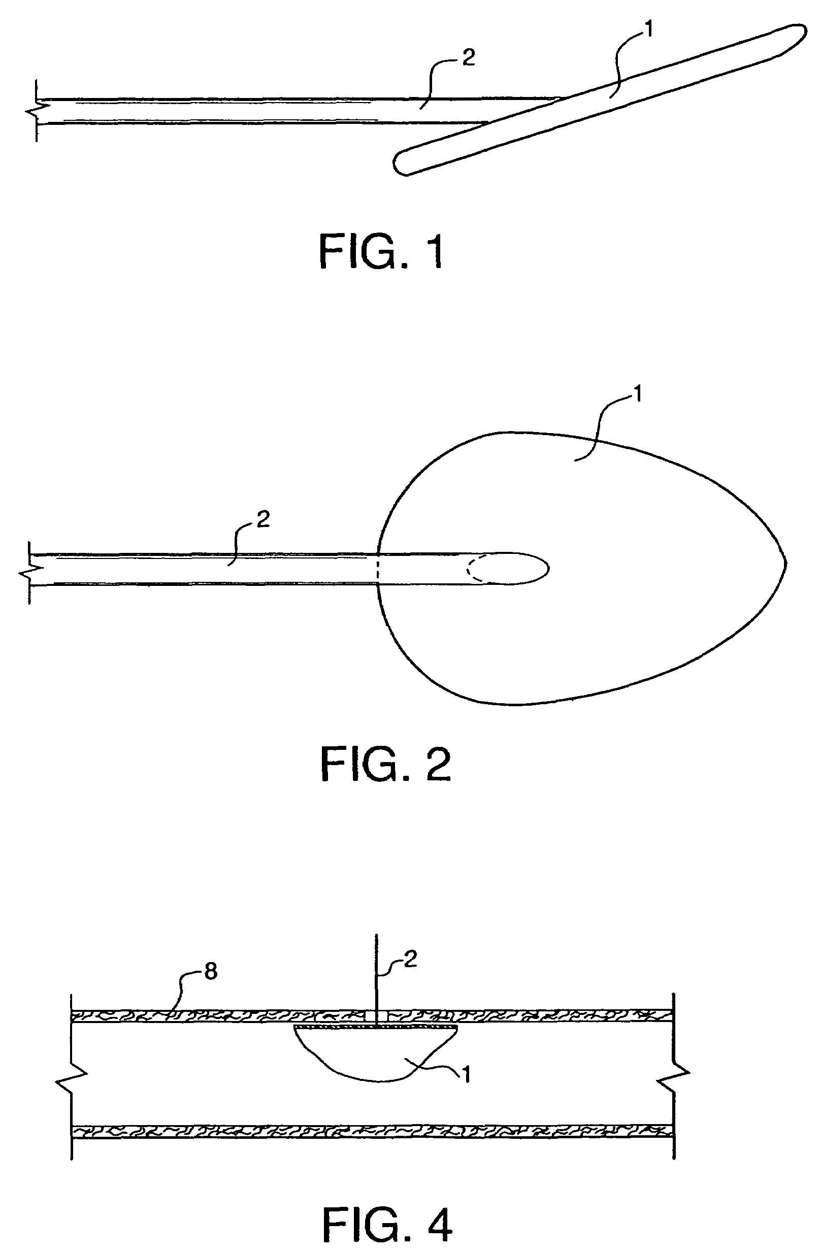
[0023]A first embodiment of the sealing device in accordance with the invention is shown in the form of a side view in FIG. 1. This comprises a flexible sheet 1 as the sealing element and, in the center connected thereto, a fixation attachment 2, fashioned here in the form of a thread. The same arrangement is sketched in the form of a view from above in FIG. 2.

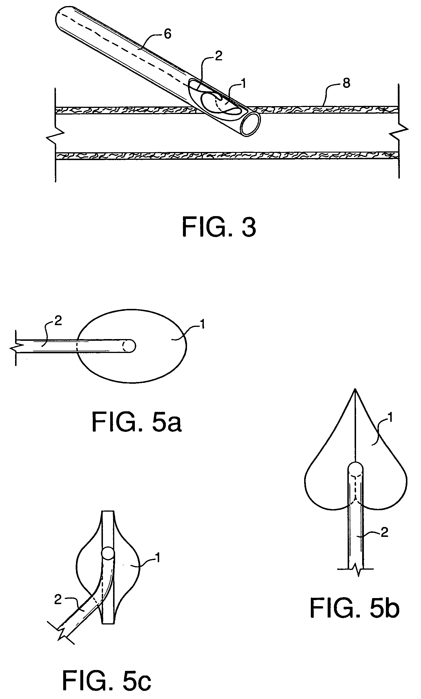
[0024]A blood vessel 8 is illustrated in FIG. 3 in which a sheath 6 has been introduced as is carried out for various types of medical applications. After removing the sheath 6, the problem existed until now that a considerable opening arose in the blood vessel which had to be sealed in some way. The means described in the prior art for effecting such sealing have been found to be unreliable or to impose restrictions on the patient in terms of his or her movement. In accordance with the invention, the device portrayed in FIGS. 1 and 2 is inserted through the sheath as illustrated. After the sealing element 1 has been introduce...


PUM


Abstract

A percutaneously insertable system for sealing punctures in blood vessels includes an element that is percutaneously insertable into and deplorable within a blood vessel, a thread-like member attached to the element that passes through the wall of the blood vessel and arresting element movable on the thread and into engagement with the other surface of the blood vessel thereby to seal the opening.

Description

RELATED APPLICATIONS[0001]This application is a continuation of application Ser. No. 09 / 617,286, filed Jul. 17, 2000 now U.S. Pat. No. 6,764,500, which is a continuation of application Ser. No. 08 / 837,965, filed Apr. 14, 1997, now U.S. Pat. No. 6,190,400, issued Feb. 20, 2001, which is a continuation of Ser. No.08 / 369,264, filed Jan. 5, 1995, now U.S. Pat. No. 5,620,461, issued Apr. 15, 1997, which is a continuation of application Ser. No. 08 / 187,788, filed Jan. 26, 1994 now abandoned, which is a continuation of application Ser. No. 07 / 781,091, filed Oct. 22, 1991 now abandoned.BACKGROUND OF THE INVENTION[0002]The invention is concerned with a sealing device for the closure of puncture holes in blood vessels.[0003]In the case of invasive investigations and intervention in medical practice, it is necessary that access be gained to the system of blood vessels in question (arterial or venous). This can take place surgically by direct vision or by way of percutaneous puncture whereby th...

Claims


Application Information

Patent Timeline
IPC IPC(8): A61B17/08A61B17/00A61B17/22A61F2/06
CPCA61B17/0057A61B2017/00637A61F2/06A61B2017/00659A61B2017/00641
Inventor MUIJS VAN DE MOER, WOUTER MATTHIJSRIENKS, RIENK
Owner KENSEY NASH CORP
Why Eureka
Try Eureka