Magnetron executing planetary motion adjacent a sputtering target

a planetary motion and magnetosphere technology, applied in the field of materials sputtering, can solve the problems of high temperature operation with possible damage, severely affecting the performance and reliability of the resulting device, and the sputtering is not inherently adapted to sidewall coverage, etc., to achieve complete target utilization, increase plasma density, and increase the effect of uniform sputtering

Inactive Publication Date: 2007-01-30
APPLIED MATERIALS INC
View PDF19 Cites 11 Cited by
  • Summary
  • Abstract
  • Description
  • Claims
  • Application Information

AI Technical Summary

Benefits of technology

[0019]A planetary magnetron may be used in a plasma sputter reactor for increased uniformity of sputtering, more complete target utilization, and increased plasma density.
[0021]Retrograde planetary motion with the rotation ratio between the planetary and orbital rotations being near unity allows the magnetron velocity to be much faster at the center of the target than at the target periphery. Rotation ratios of 1.03 to 6 as measured by gear ratios or other engagement ratios are preferred but integral values should be avoided. Rotation ratios from about 1.2 to about 1.66 and from about 2.5 to 4.97 provide a significantly larger velocity at the target periphery than the target center, thereby producing more uniform sputtering of the target.

Problems solved by technology

Sputtering is fundamentally a generally isotropic ballistic process ill suited to reaching into high aspect-ratio holes.
Again, sputtering is not inherently adapted for sidewall coverage.
The resulting void in the copper severely affects the performance and reliability of the resulting device.
However, inductively coupled reactors tend to require high argon pressures and result in a high-temperature operation with possible damage from the energetic argon ions being accelerated to the wafer.
However, for the 300 mm wafer technology being developed and even for 200 mm wafers, this approach causes the required power supplies to become prohibitively expensive, and controlling the target temperature becomes difficult.
In contrast, inductively coupled reactors require inductive coils in an expensive new design, and hollow cathode or vaulted target reactors expensive complexly shaped targets.
The unbalanced magnetic field results in magnetic field lines projecting far from the stronger outer pole towards wafer.
Although the rotating triangular magnetron provides reasonably adequate uniformity, uniformity for thin barrier layers in high-aspect ratio holes is a complex requirement, as has been partially discussed with reference to FIG. 3.
The projecting magnetic field from the unbalanced triangular magnetron is very non-uniform in the radial direction, and its non-uniformity cannot be compensated by only circumferential scanning.
Various types of auxiliary magnets have been proposed to compensate the inherent non-uniform magnetic field in a triangular magnetron, but these designs suffer their own deficiencies.
Another problem with circumferentially scanned magnetrons is the typically non-uniform erosion in the radial direction.
This problem arises even when the magnetron has a rather large size, such as the kidney-shaped magnetron.
It is difficult to achieve high utilization of the target center with only circumferential scanning of the small magnetron favored for SIP sputtering.
Although the non-uniform erosion is reduced with the use of large kidney-shaped magnetron, it still occurs to a significant degree.
Further sputtering would contaminate the wafer with the non-desired material of the backing plate, and the target must be discarded or at least refurbished with a new target layer.
However, overall target utilization is poor, about 50% in the illustrated example.
When an integral target is used without a distinct backing plate, as is typical for aluminum sputtering, the considerations are somewhat different, but poor target utilization resulting from erosion tracks is still a problem.
A problem arises with magnetron sputtering being used for a variety of applications with differing requirements on the shape and intensity of the magnetic field.
While satisfactory sputtering reactors have been designed for most of these applications, often the reactors and their magnetrons have substantially different designs.
The increasing number of different types of reactors and magnetrons imposes economic and inventory penalties in designing, distributing, and maintaining so many different types of reactors.
The Freeman design seems more practical, but it suffers from an inability to rotate the magnetron over the target center, and it is prone to excessive vibration.
The Tomer design allows for center scanning, but its stationary internally toothed circumferential gear is unwieldy.

Method used


Image

  • Magnetron executing planetary motion adjacent a sputtering target
  • Magnetron executing planetary motion adjacent a sputtering target
  • Magnetron executing planetary motion adjacent a sputtering target

Examples


Embodiment Construction

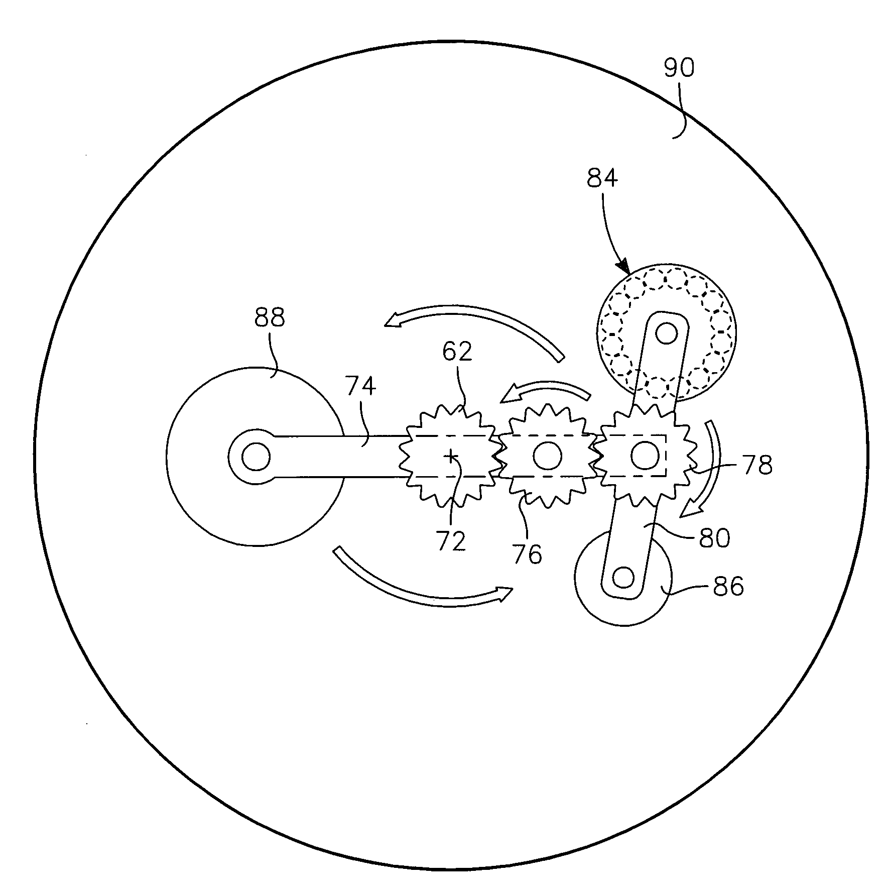
[0045]One principal embodiment of the invention relies upon a planetary mechanism, for instance, one using a planetary gear system, to allow a small circularly symmetric magnetron to fully cover the sputtering target. The planetary mechanism produces a planetary motion similar to that of a planet orbiting the sun while it is simultaneously executing planetary rotation about its own polar axis. For use with a magnetron, the planetary axis is parallel to but displaced from the orbital axis and the orbit is circular about the orbital axis. The magnet assembly of the magnetron is displaced from and rotates about the planetary axis while the planetary axis orbits or rotates about the orbital axis, thereby producing a complex trajectory for the magnetron. In retrograde planetary motion, the direction of planetary rotation is the reverse to the direction of orbital rotation.

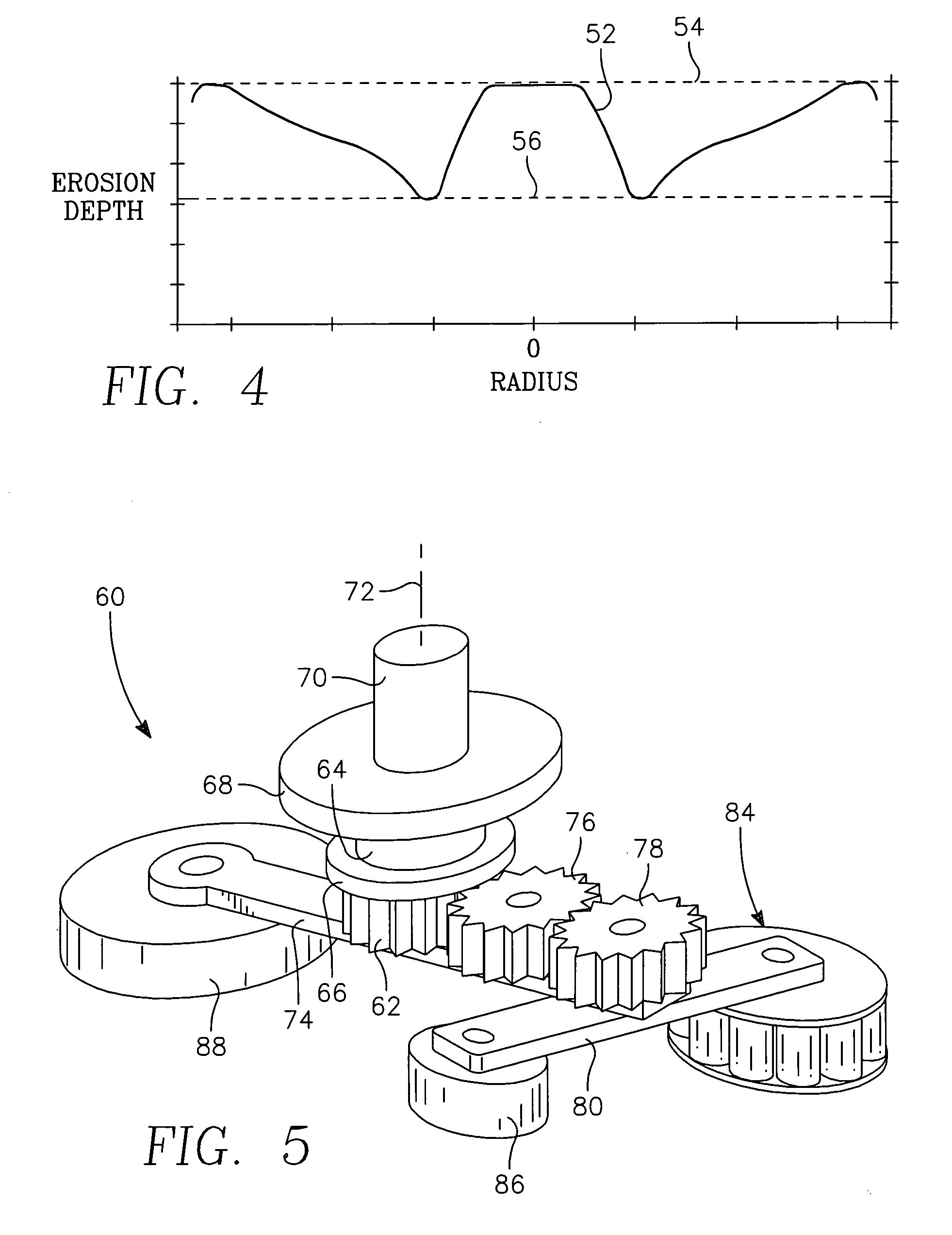
[0046]In one geared embodiment illustrated in the orthographic view of FIG. 5, a magnetron assembly 60 includes a fix...


PUM

PropertyMeasurementUnit
widthaaaaaaaaaa
sizesaaaaaaaaaa
sizesaaaaaaaaaa

Abstract

A small magnet assembly is scanned in a retrograde planetary or epicyclic path about the back of a target being plasma sputtered including an orbital rotation about the center axis of the target and a planetary rotation about another axis rotating about the target center axis. The magnet assembly passes through the target center, thus allowing full target coverage. A properly chosen ratio of the two rotations about respective axes produces a much slower magnet velocity near the target periphery than at the target center. A geared planetary mechanism includes a rotating drive plate, a fixed center gear, and an idler and a follower gear rotatably supported in the drive plane supporting a cantilevered magnet assembly on the side of the drive plate facing the target. A belted planetary mechanism includes a fixed center capstan, a follower pulley supporting the magnet assembly, and a belt wrapped around them.

Description

RELATED APPLICATION[0001]This application is a continuation of Ser. No. 10 / 152,494, filed May 21, 2002, now issued as U.S. Pat. No. 6,841,050.FIELD OF THE INVENTION[0002]The invention relates generally to sputtering of materials. In particular, the invention relates to the magnetron creating a magnetic field to enhance plasma sputtering.BACKGROUND ART[0003]Sputtering, alternatively called physical vapor deposition (PVD), is commonly used in the fabrication of semiconductor integrated circuits for depositing layers of metals and related materials particularly for the formation of electrical interconnections. Somewhat older integrated circuit technology uses aluminum for horizontal interconnects and for vertical interconnects between metallization levels through vias having relatively modest aspect ratios. Such applications require fast deposition rates and high uniformity that are easily achievable with sputtering. The fast deposition rate has been achieved in part by magnetron plasm...

Claims


Application Information

Patent Timeline
Patent Type & Authority Patents(United States)
IPC IPC(8): C23C14/35C23C14/32H01J37/34
CPCC23C14/345C23C14/35H01J37/3455H01J37/3405H01J37/3408C23C14/355
Inventor HONG, ILYOUNG RICHARDTSUNG, JAMESLUBBEN, DANIEL CLARENCEDING, PEIJUNMAITY, NIRMALYA
Owner APPLIED MATERIALS INC
Why Eureka
Try Eureka