Method for loading filament in an extrusion apparatus

a technology of extrusion apparatus and filament, which is applied in the direction of molds, process and machine control, program control, etc., can solve the problems of inability to meet the requirements of production,

Inactive Publication Date: 2007-01-30
STRATSYS INC
View PDF75 Cites 68 Cited by
  • Summary
  • Abstract
  • Description
  • Claims
  • Application Information

AI Technical Summary

Benefits of technology

[0013]The filament loading method of the present invention provides a convenient manner of loading and unloading filament in a three-dimensional modeling machine, and can be implemented in a manner that protects the filament from environmental moisture.

Problems solved by technology

Manually feeding filament to the head, as is presently done, can be tedious.
Additionally, as a practical matter, users often leave old desiccant in the drybox and fail to replace it with new desiccant, allowing humidity in the drybox to reach unacceptable levels.
Further, frequent switching of spools results in moisture-contaminated material.
A partially used spool unloaded from the machine is exposed to moisture and becomes contaminated as well.
These moisture contamination problems result in wasted material when the user switches the type or color of modeling material.
Moreover, some materials desirable for use as modeling materials in the Stratasys FDM® machines are highly vulnerable to moisture and can get contaminated within minutes.
The time during which the drybox door is opened for loading and unloading filament introduces a level of moisture into the drybox unacceptable for some desirable materials, limiting the choice of modeling materials for use in these machines.

Method used


Image

  • Method for loading filament in an extrusion apparatus
  • Method for loading filament in an extrusion apparatus
  • Method for loading filament in an extrusion apparatus

Examples


embodiment one

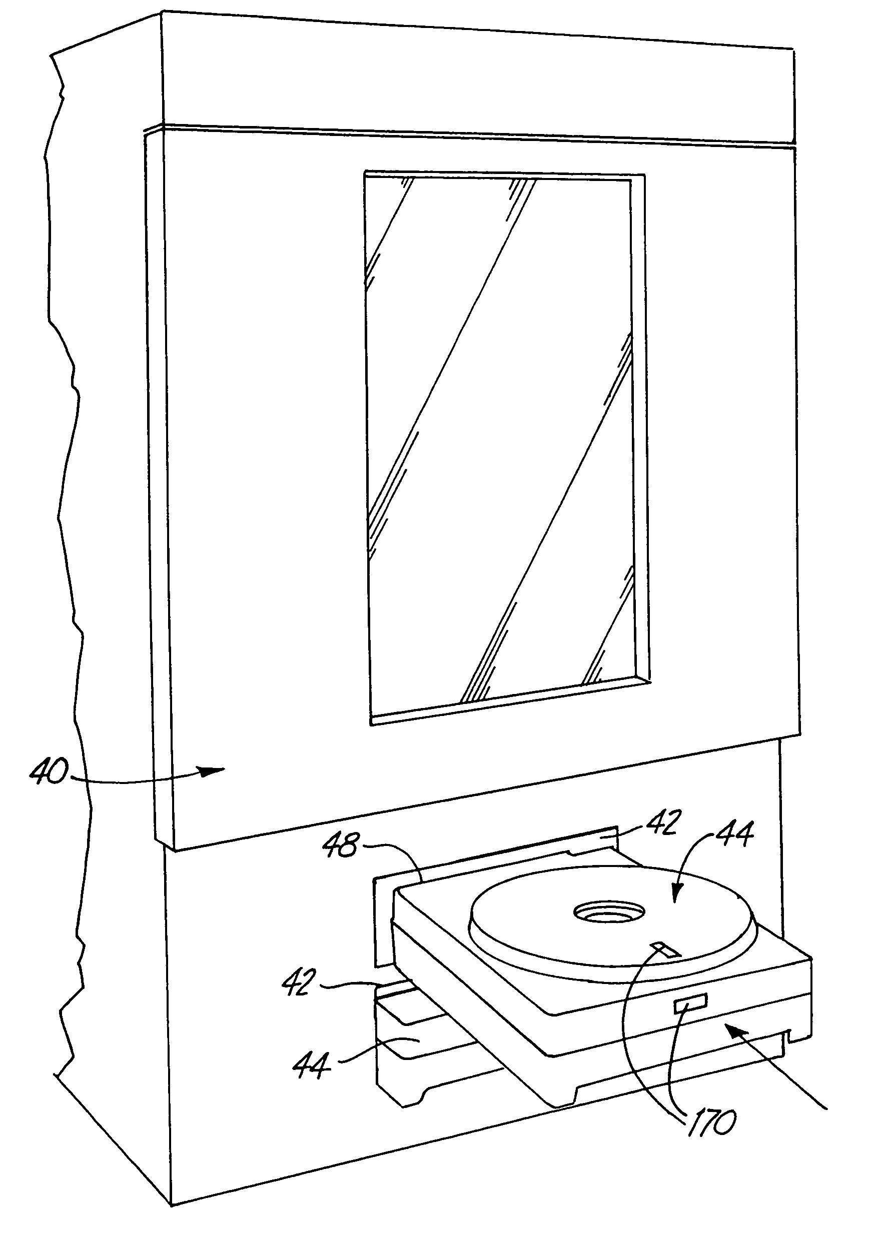
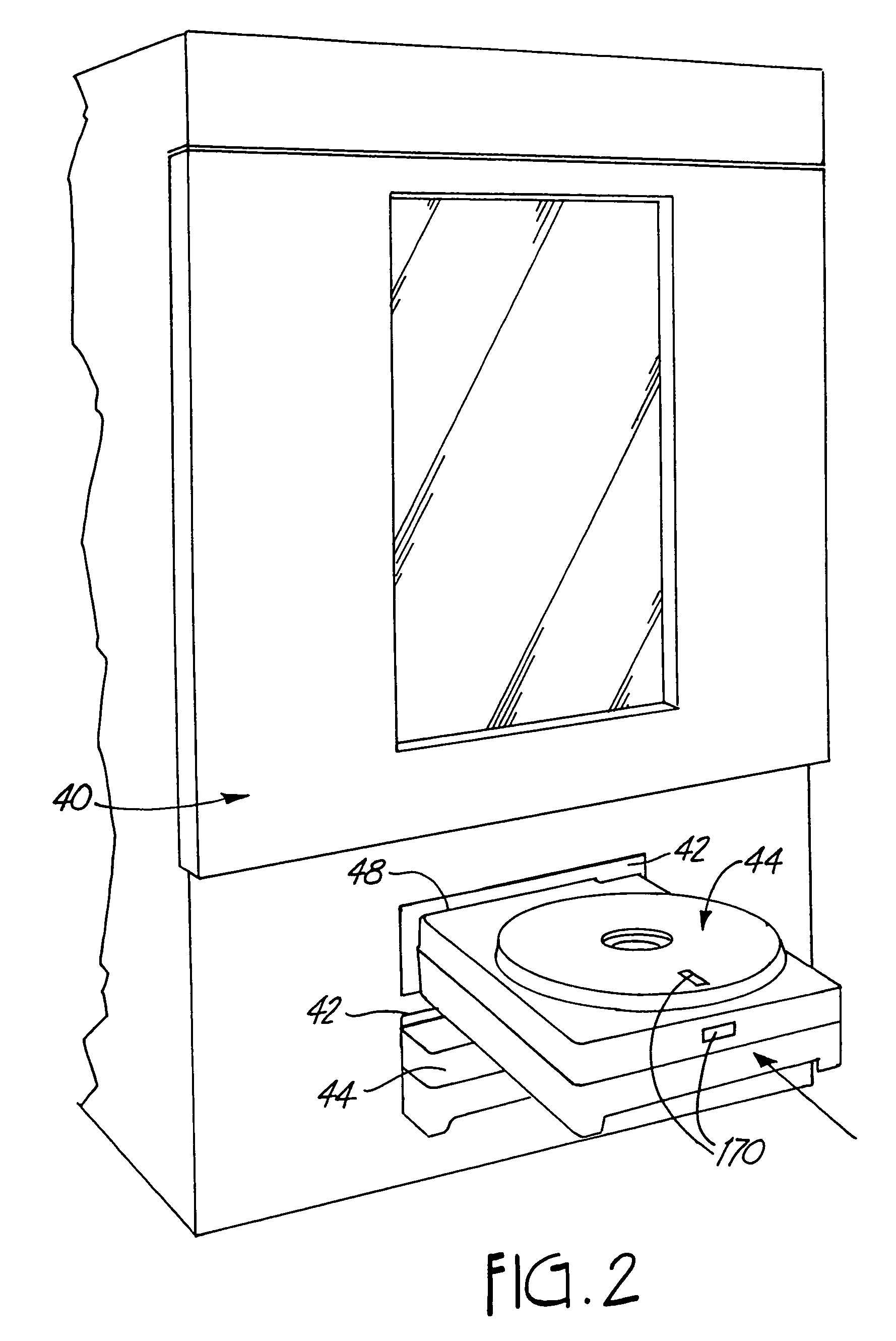
[0039]In the present invention, the spool carrying a coil of filament is contained within a filament cassette. FIG. 2 shows a first exemplary embodiment of a modeling machine 40 which has two loading bays 42 stacked vertically, each for receiving a first embodiment of a filament cassette 44. As shown, one filament cassette 44 is loaded into the lower loading bay. A second cassette 44 is being loaded into the upper loading bay 42. Each filament cassette contains a spool carrying a coil of filament. Preferably, one cassette 44 supplies filament formed of modeling material, while the other cassette 44 supplies filament formed of support material. The modeling machine 40 has two liquifiers 26, such as shown in FIG. 1, which each receive a strand of filament from one of the cassettes 44.

[0040]As will be described in detail below, each loading bay 42 contains a cassette receiver 46 which engages the filament cassette 44 and advances a strand of the filament 14 from the cassette 44 into th...

embodiment two

[0064]FIG. 13 shows a filament loading assembly 178 in a second embodiment of a modeling machine 180, which builds models from filament supplied from a second exemplary embodiment of a filament cassette 184. The filament loading assembly 178 and the filament cassette 184 are particularly suited for building models from moisture-sensitive materials. The filament loading assembly 178 comprises four loading bays 182, four filament cassettes 184 each containing a spool 186 carrying a coil of filament 188, four filament cassette receivers 190, two junction blocks 192 and a drying system 194. The four loading bays 182 are aligned horizontally across the front of the modeling machine 180. Each loading bay 182 receives one filament cassette 184 and has associated with it one filament cassette receiver 190, mounted in a ceiling thereof. The junction blocks 192 are mounted to a frame 195 of the filament loading assembly 178, and are each associated with a pair of cassette receivers 190.

[0065]...


PUM

PropertyMeasurementUnit
diameteraaaaaaaaaa
temperatureaaaaaaaaaa
lengthaaaaaaaaaa

Abstract

Filament is loaded into an extrusion apparatus, such as a three-dimensional deposition modeling machine, by inserting a cassette containing filament into the apparatus. A filament strand from the cassette is then advanced into the machine, such as by operating a thumb wheel or a follower wheel on the cassette. The filament loading method of the present invention provides a convenient manner of loading and unloading filament in a three-dimensional modeling machine, and can be implemented in a manner that protects the filament from environmental moisture.

Description

CROSS-REFERENCE TO RELATED APPLICATION(S)[0001]This application is a divisional of application Ser. No. 09 / 804,401, filed on Feb. 27, 2001, issued on Oct. 17, 2004 as U.S. Pat. No. 6,776,602, which claims priority to provisional application Ser. No. 60 / 218,642, filed Jul. 13, 2000, and which is also a continuation-in-part of PCT International Application No. PCT / US00 / 17363, filed on Jun. 23, 2000 (designating the United States), which is hereby incorporated by reference as if set forth, and which is a non-provisional of provisional application Ser. No. 60 / 140,613, filed Jun. 23, 1999.BACKGROUND OF THE INVENTION[0002]This invention relates to the fabrication of three-dimensional objects using extrusion-based layered manufacturing techniques. More particularly, the invention relates to forming three-dimensional objects by extruding solidifiable modeling material in a flowable state in three dimensions with respect to a base, wherein the modeling material is supplied in the form of a f...

Claims


Application Information

Patent Timeline
Patent Type & Authority Patents(United States)
IPC IPC(8): B29C41/34B29C31/00B29C41/36B29C41/52B29C67/00B29C71/02C08K5/00
CPCB29C41/36B29C67/0055B29C67/0092C08K5/0016C08L33/02B29C31/04B29C41/52B29C71/02Y10T29/49826B29C2791/005B29K2055/02G05B2219/49019B29C2071/022B29C64/40B33Y40/00B33Y30/00B33Y70/00B29C64/118B29C64/106
Inventor SWANSON, WILLIAM J.POPA, MIHNEA A.TURLEY, PATRICK W.HOPKINS, PAUL E.BROSE, STEVEKIMM, DANIEL I.POLLARD, DAVID L.HAHN, ANDREW M.
Owner STRATSYS INC
Why Eureka
Try Eureka