
Configurable multiple power source system

a power source system and configuration technology, applied in the field of powering systems, can solve the problems of underutilized dedicated external power supply and insufficient utilization of internal power supply

Inactive Publication Date: 2007-01-30
NEVERMORE SOLUTIONS
View PDF29 Cites 99 Cited by
  • Summary
  • Abstract
  • Description
  • Claims
  • Application Information

AI Technical Summary

Benefits of technology

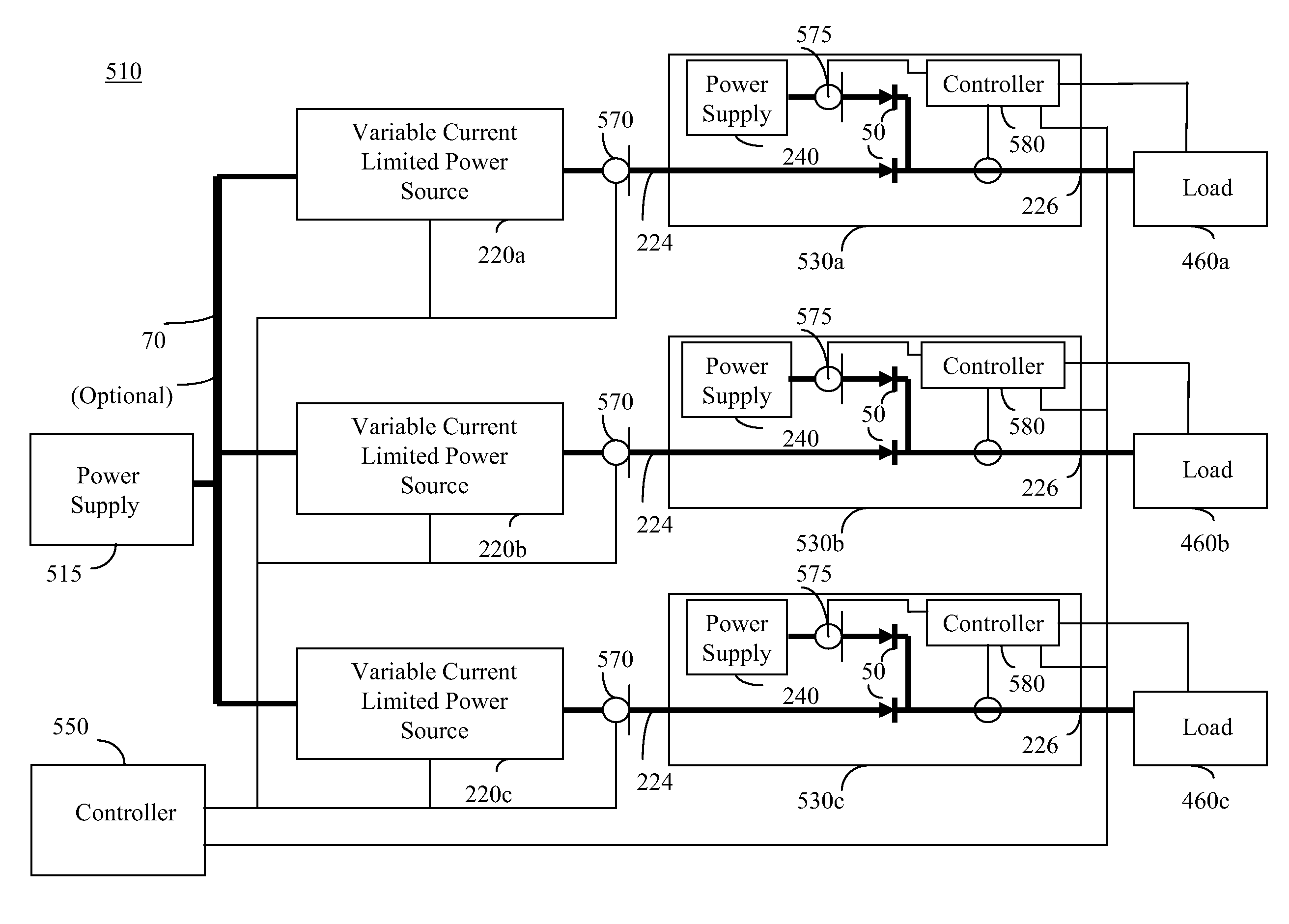
[0026]Independently, the invention also provides for a system for supplying additional power and back-up power to at least one load, the system comprising: a first power supply; a boost converter having a first variable current limiter, the boost converter being connected to an output of the first power supply; at least one load; a second power supply associated with the load, the second power supply having a voltage output less than the voltage output of the boost converter; and a second variable current limiter limiting the current flow from the first power supply to the at least one load, wherein the output of the second variable current limiter is connected in a wired or configuration to cooperatively supply power with the second power supply to the at least one load, and whereby in the event of a failure of the second power supply, the voltage output of the boost converter is substantially the same as the voltage output of the first power supply, and power to the load is limited by the second variable current limiter.
[0027]In one embodiment the system further comprises a controller operable to control the second variable current limiter. In a further embodiment the controller is further operable to control the first variable current limiter.

Problems solved by technology

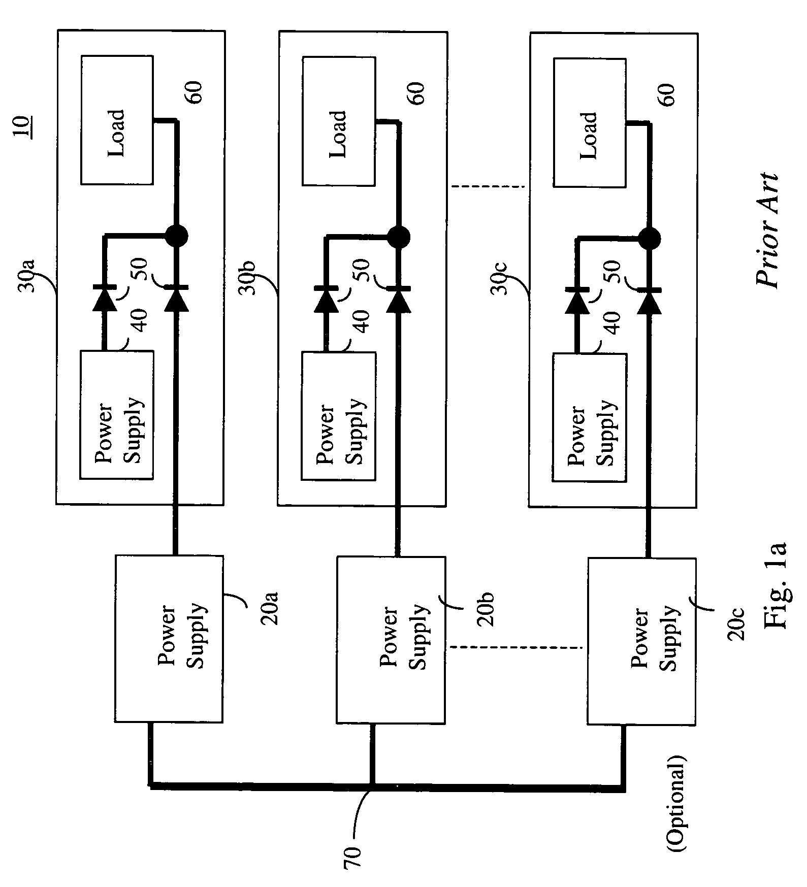
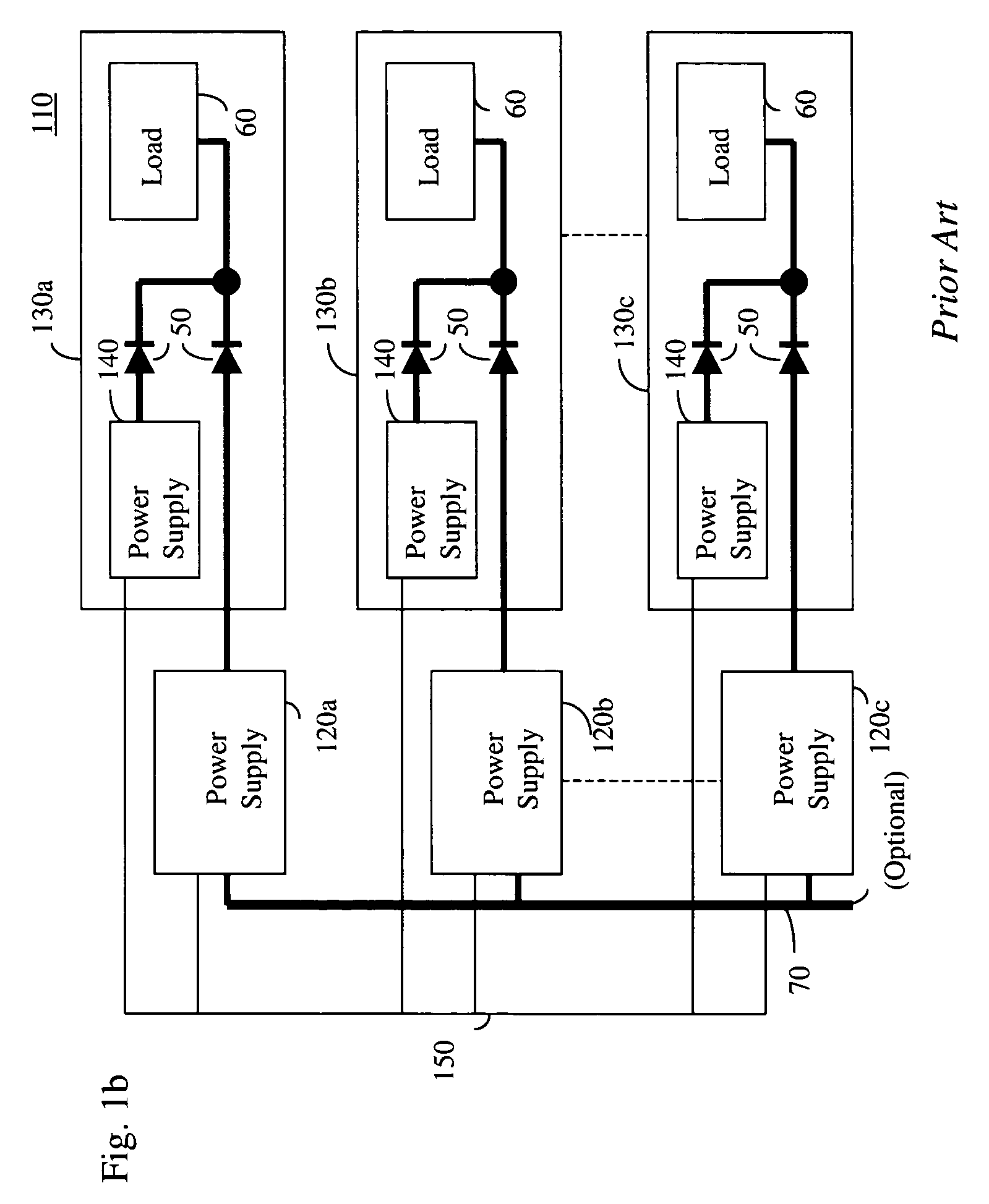
Such a dedicated external power supply is often underutilized, only experiencing optimum utilization as the system power needs grow.
Furthermore, the internal power supply is not being utilized except as a back-up.

Method used


Image

  • Configurable multiple power source system
  • Configurable multiple power source system
  • Configurable multiple power source system

Examples


Embodiment Construction

[0050]The present embodiments enable load sharing by multiple power sources. In a preferred embodiment at least one of the power sources is an internal power supply associated with and supplying power to a load and at least one power source is an external variable current limited power source supplying additional power to the load. Control of the external variable current limited power source is accomplished in response to monitored information related to the load power requirements, and additional power is added without the need to adjust the internal power supply. In a preferred embodiment the output of the external variable current limited power source and internal power supply are combined in a “wired or” configuration to supply a combined power to the load without control over the internal power supply.

[0051]Before explaining at least one embodiment of the invention in detail, it is to be understood that the invention is not limited in its application to the details of construc...


PUM


Abstract

A system for supplying additional power to a module having an internal power supply, the system comprising: a module having an associated power supply, the power supply not being designed to accommodate power sharing; at least one load associated with the module, the load receiving power from the power supply; a variable current limited power source connected to the module supplying additional power to the at least one load; and a controller; whereby the variable current limited power supply is responsive to an output of the controller to vary the current limit of the variable current limited power supply.

Description

CROSS-REFERENCE TO RELATED APPLICATIONS[0001]The present application is a continuation-in-part of U.S. patent application Ser. No. 10 / 750,908 filed Jan. 5, 2004, whose entire contents are incorporated herein by reference, which claims priority from PCT Patent Application No. PCT / IL03 / 00832 filed Oct. 14, 2003, which claims priority from U.S. Provisional Patent Application No. 60 / 418,599 filed Oct. 15, 2002, whose entire contents are incorporated herein by reference.BACKGROUND OF THE INVENTION[0002]The present invention relates to the field of powering a system comprising modules having internal power supplies, and in particular to a system and entities for variably supplying additional power to at least one module having an internal power supply.[0003]Systems, such as communication systems, commonly comprise modules having internal power supplies connected to an A / C mains. In order to provide uninterrupted operation, systems often comprise a back-up power supply (BUPS) which, during...

Claims


Application Information

Patent Timeline
Patent Type & Authority Patents(United States)
IPC IPC(8): H02J1/10H02J7/34H02J9/06
CPCH02J1/10H02J9/061H02M2001/008H02M1/008
Inventor KORCHARZ, DRORDARSHAN, YAIRATIAS, ILANPINCU, DAVID
Owner NEVERMORE SOLUTIONS
Learn More