Rapid charger for ultracapacitors

a technology of ultracapacitors and chargers, applied in the direction of electrochemical generators, secondary cell servicing/maintenance, transportation and packaging, etc., can solve the problem of limited rate and achieve the effect of faster rate and faster recharging of depleted ultracapacitors

Inactive Publication Date: 2007-01-30
TESLA INC
View PDF11 Cites 25 Cited by
  • Summary
  • Abstract
  • Description
  • Claims
  • Application Information

AI Technical Summary

Benefits of technology

[0006]The disclosed embodiments of the present invention provide systems and methods for recharging an ultracapacitor at a faster rate th

Problems solved by technology

Although this provides a constant recharge rate, the rate is

Method used


Image

  • Rapid charger for ultracapacitors
  • Rapid charger for ultracapacitors
  • Rapid charger for ultracapacitors

Examples


Embodiment Construction

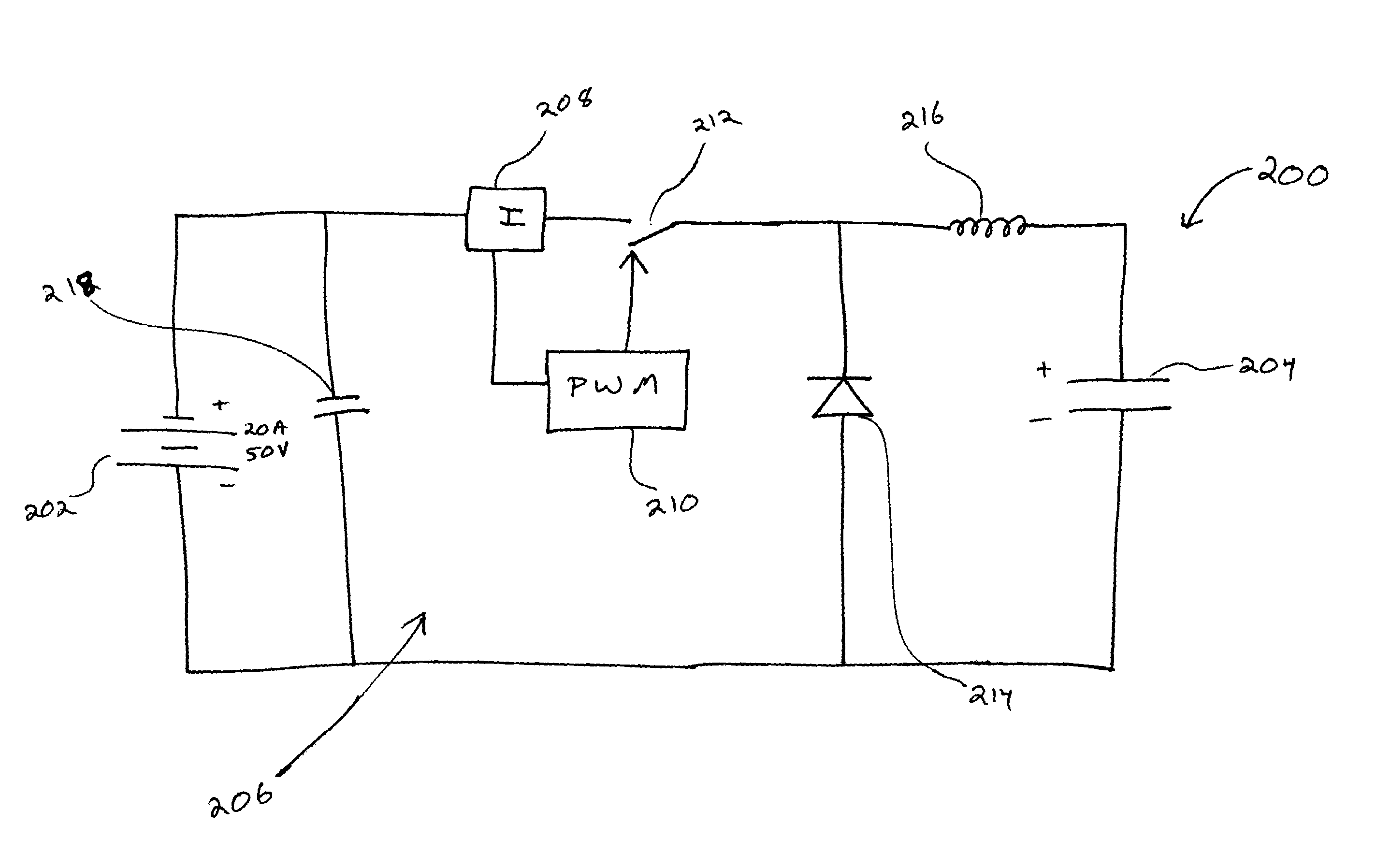
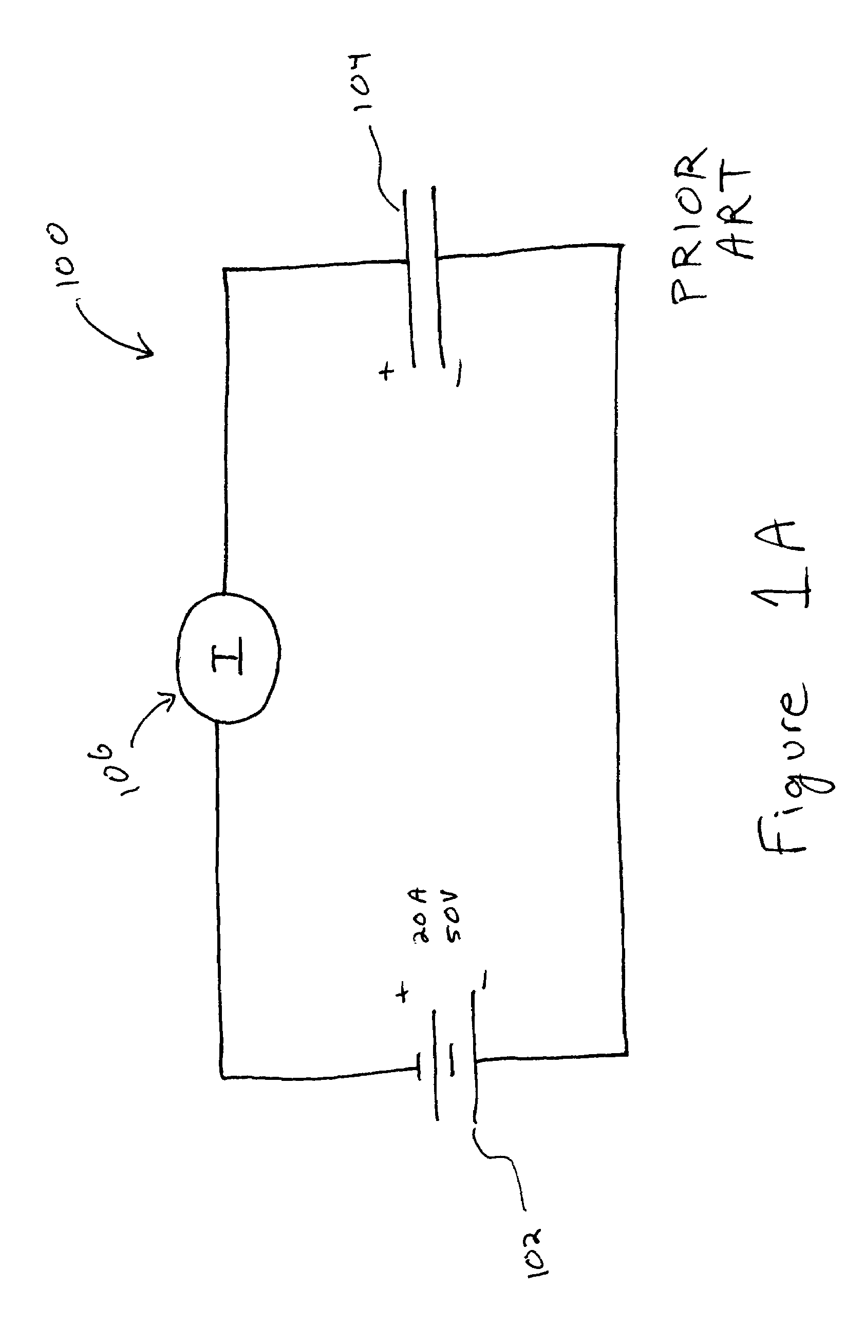
[0022]The present invention is generally directed to rapid charging systems and methods for recharging ultracapacitor power modules. In this regard, the present invention allows the rapid charging of ultracapacitors, thereby significantly reducing the time required for recharging, for example, a bank of ultracapacitors.

[0023]Ultracapacitors are well known to those skilled in the art as an efficient energy storage system. Ultracapacitor power modules can include a bank of ultracapacitors connected in series to provide a desired voltage level for the particular application. One attractive feature of ultracapacitors as an energy source is the relatively short recharge times once the ultracapacitors are completely or partially depleted.

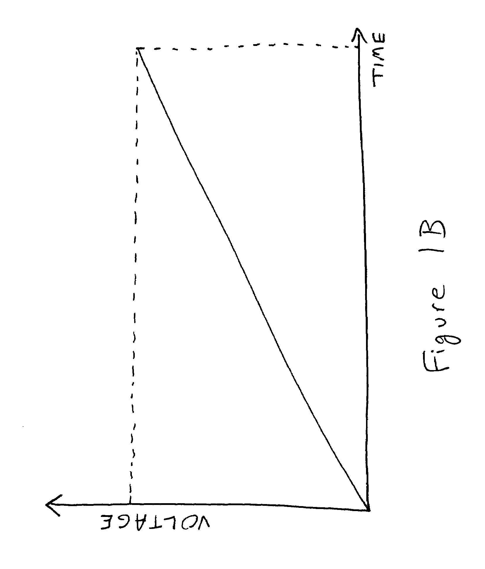
[0024]The recharge rate of a capacitor, an ultracapacitor or a bank of ultracapacitors in a power module can be described by the following equation:

dV / dt=I / C,

where dV / dt is the rate of increase of voltage in the ultracapacitor, I is the current through t...


PUM


Abstract

A rapid charging circuit for charging a power module is disclosed. The power module includes one or more ultracapacitors. The power module is charged using an energy source connected to the power module. The charging circuit includes a control circuit adapted to maintain a constant power level at the power module during charging as the voltage level across the power module increases. The control circuit includes a pulse-width modulator and an inductor connected in series with the power module. The pulse-width modulator can control a charge level of the inductor. The charge level may correspond to a current level which is in accordance with a desired power level at the power module and an instantaneous voltage level across the power module. The inductor may be adapted to limit a current level through the power module to a predetermined peak level. The control circuit may be adapted to provide a current level through the power module greater than a current level from said energy source during at least a portion of a charging period.

Description

FIELD OF THE INVENTION[0001]The present invention relates generally to energy storage systems. More particularly, the invention relates to methods and systems for charging energy storage systems which incorporate ultracapacitors.BACKGROUND[0002]The following description is provided to assist the understanding of the reader. None of the information provided or references cited is admitted to be prior art to the present invention.[0003]Ultracapacitors can be an excellent source of energy in many applications. They offer several advantages over other types of energy storage systems such as batteries. For example, once depleted, ultracapacitors can be recharged at a significantly faster rate than batteries. Under ideal conditions, the recharge rate can be as high as the discharge rate.[0004]Existing recharges for ultracapacitors generally provide a constant current through the ultracapacitor to provide recharging energy. Although this provides a constant recharge rate, the rate is limit...

Claims


Application Information

Patent Timeline
IPC IPC(8): H01M10/44H01M10/46H02J1/00H02J7/34
CPCH02J7/345H02J7/00712H02J7/007182H02J7/00714H02J2207/50
Inventor THRAP, GUY C.
Owner TESLA INC
Why Eureka
Try Eureka