Phased array antenna interconnect having substrate slat structures

a phased array and substrate technology, applied in the direction of slot antennas, waveguides, antennas, etc., can solve the problems of complicated phased array antennas, complicated rapid beam scanning, and inability to integrate phased arrays into the most sophisticated and expensive military and commercial applications

Active Publication Date: 2007-01-30
ADVANCED HEALTH MEDIA +1
View PDF3 Cites 89 Cited by
  • Summary
  • Abstract
  • Description
  • Claims
  • Application Information

AI Technical Summary

Problems solved by technology

Radical vehicular platform movement, e.g., high performance fighter aircraft “dog fighting” maneuvers, further complicates the need for rapid beam scanning.
Despite the benefits of phased array antennas described above, phased array antennas are often only integrated into the most sophisticated and expensive military and commercial applications due to prohibitively high costs.
In addition, a Solid State Phased Array (SSPA) is further complicated by the fact that high bias currents often dictate liquid cooling to maintain power amplifier transistor-junction temperatures at reliable levels to ensure adequate system operational lifetimes.

Method used


Image

  • Phased array antenna interconnect having substrate slat structures
  • Phased array antenna interconnect having substrate slat structures
  • Phased array antenna interconnect having substrate slat structures

Examples


Embodiment Construction

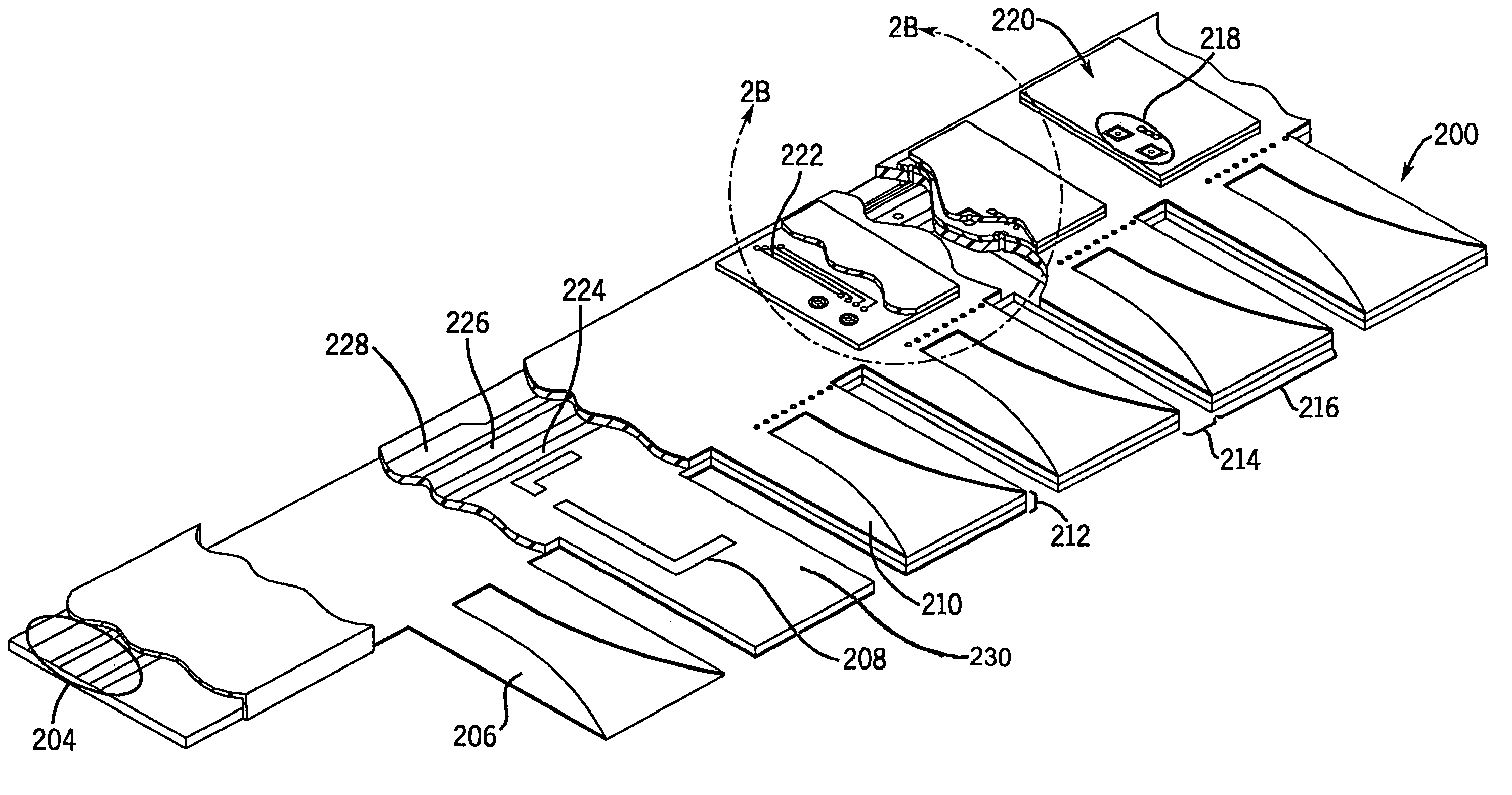
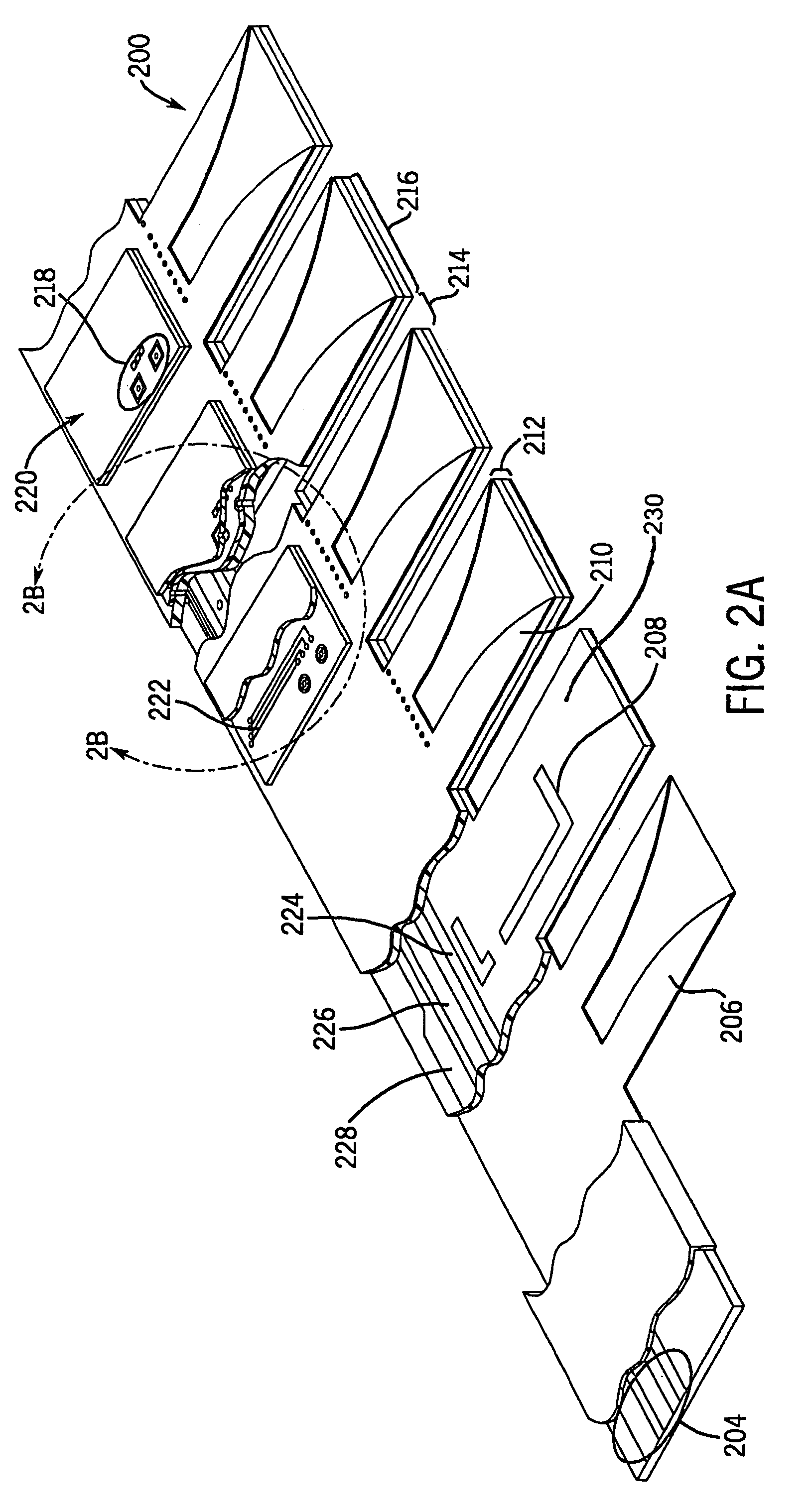
[0017]A phased array antenna interconnect structure is provided that reduces the number of electrical connections required to provide RF signals and bias / control signals to multiple radiating elements and phase shifters, respectively, of the phased array antenna and provides a cost effective phased array antenna architecture that has a single locus of electrical connection for RF signals and bias / control signals embedded in a multi-layer linear array or slat substrate of the phased array antenna.

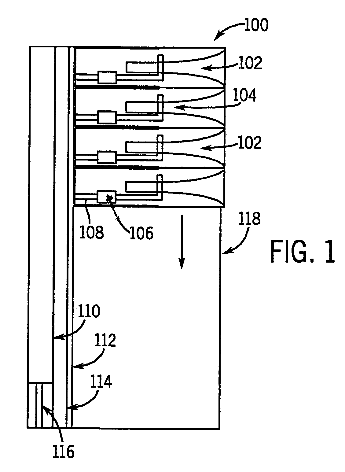
[0018]A phased array antenna may be created using unit cells comprising a radiating element. A linear array or slat may be formed by placing multiple radiating elements on an interconnect substrate (e.g., a common printed wiring board (PWB) substrate). FIG. 1 illustrates a linear array (or slat) having multiple radiating elements with integral phase shifters in accordance with an embodiment. Linear array (or slat) 100 comprises multiple radiating elements 102 on a common substrate 118. In FI...


PUM


Abstract

A phased array antenna is provided having a plurality of phase shifter devices for phase shifting and beam steering a radiated beam of the phased array antenna. The plurality of phase shifter devices are interconnected with an interconnect structure comprising a plurality of linear array substrate slats. Each linear array substrate slat includes a plurality of radiating elements formed using first and second metal layers of the substrate slat, a plurality of phase shifter devices and a common RF feed conductor for the plurality of radiating elements. The common RF feed conductor is formed on a third metal layer of the substrate slat that is disposed between the first and second metal layers. The common RF feed conductor is configured to include a single location for electrical connections to receive RF signals for the plurality of radiating elements. The phased array antenna also includes bias / control conductors applied to selected areas of the third metal layer, a fourth metal layer applied over the second metal layer and a shielding metal layer applied on the fourth metal layer. The bias / control conductors are configured to include a single location for electrical connections to receive bias voltages and control signals. The fourth metal layer includes circuit connections from the bias / control circuitry to the plurality of phase shifter devices. Each phase shifter device is attached to a radiating element via a mounting location on the shielding metal layer. Accordingly, a phased array antenna interconnect structure is provided that reduces the number of electrical connections required to provide RF signals and bias / control signals to multiple radiating elements and phase shifters, respectively, of the phased array antenna and provides a cost effective phased array antenna architecture that has a single locus of electrical connection for RF and bias control signals embedded in a multi-layer linear array or slat substrate of the phased array antenna.

Description

CROSS-REFERENCE TO RELATED PATENT APPLICATIONS[0001]The present application is related to application Ser. No. 10 / 273,872, filed Oct. 18, 2002, now U.S. Pat. No. 6,822,617 entitled “A Construction Approach for an EMXT-Based Phased Array Antenna,” and to application Ser. No. 10 / 273,459, filed Oct. 18, 2002, now U.S. Pat. No. 6,950,062, entitled “A Method and Structure for Phased Array Antenna Interconnect,” both of which applications are herein incorporated by reference in their entirety. All applications are assigned to the assignee of the present application.FIELD OF THE INVENTION[0002]The present invention relates generally to the field of antennas, phased array antennas and in particular to a method and structure for an interconnect for broad band printed end-fire and dipole phased array antenna elements.BACKGROUND OF THE INVENTION[0003]Many military and commercial applications of satellite communication (SATCOM) and radar systems require rapid electronic beam scanning, often on ...

Claims


Application Information

Patent Timeline
Patent Type & Authority Patents(United States)
IPC IPC(8): H01P1/18H01Q3/30
CPCH01Q13/085H01Q3/30
Inventor WEST, JAMES B.MATHER, JOHN C.
Owner ADVANCED HEALTH MEDIA
Why Eureka
Try Eureka