Optically active color filter

a color filter and optically active technology, applied in the field of color filters, can solve the problems of affecting the quality of the filter, the mechanical system used to operate the roller is expensive and subject to breakdown, and the rotating roller device is only capable of producing a limited number of different colors

Inactive Publication Date: 2007-01-30
VISION QUEST LIGHTING
View PDF19 Cites 22 Cited by
  • Summary
  • Abstract
  • Description
  • Claims
  • Application Information

AI Technical Summary

Benefits of technology

[0005]In the present invention, the foregoing purposes, as well as others that will be apparent, are achieved generally by providing an optically active color filter comprising a linear polarizer, preferably a fixed-position linear polarizer, for polarizing light from an unpolarized light source, an optically active device for rotating the polarized light from the linear polarizer and an adjustable linear polarizer for selecting a desired color from the rotated polarized light coming from the optically active device. In a preferred embodiment of the present invention, the optically active device comprises an optically active liquid such as corn syrup. An advantage of the present invention is that it uses inexpensive components and is relatively easy to manufacture. As such, the present invention provides a cost-effective and economic way of producing and controlling a colored light. Further, the use of a small number of relatively simple components makes the present invention reliable and easy to maintain and operate. Other objects, features and advantages of the present invention will become apparent when the detailed description of the preferred embodiments of the invention are considered in conjunction with the drawings which should be construed in an illustrative and not limiting sense as follows.
is that it uses inexpensive components and is relatively easy to manufacture. As such, the present invention provides a cost-effective and economic way of producing and controlling a colored light. Further, the use of a small number of relatively simple components makes the present invention reliable and easy to maintain and operate. Other objects, features and advantages of the present invention will become apparent when the detailed description of the preferred embodiments of the invention are considered in conjunction with the drawings which should be construed in an illustrative and not limiting sense as follows.

Problems solved by technology

Unfortunately, the mechanical system used to operate the rollers is expensive and subject to breakdowns.
In addition, the movement of the gels can cause the gels to rip or tear.
Further, the rotating roller devices are only capable of producing a limited number of different colors because only a limited number of gels are available for positioning in the light path.
Furthermore, it takes a significant amount of time to switch between colors.
Moreover, a major disadvantage in using gels is that the colors produced by the gels are unsaturated.
Further, the gels tend to bleach out after long exposure to the high power light sources used in the foregoing devices.
Prior art devices attempt to solve the foregoing problems but each has a problem in utilization that makes it relatively unattractive to manufacture or use.
However, mechanical switching makes these devices slow in switching between colors and prone to mechanical breakdown.
In addition, such devices are relatively expensive because of the vacuum deposition process used for producing the dichroic filters.
Moreover, such devices are limited to stage lighting or film-making applications.
Other devices require complicated and / or expensive mechanisms.

Method used


Image

  • Optically active color filter
  • Optically active color filter
  • Optically active color filter

Examples


Embodiment Construction

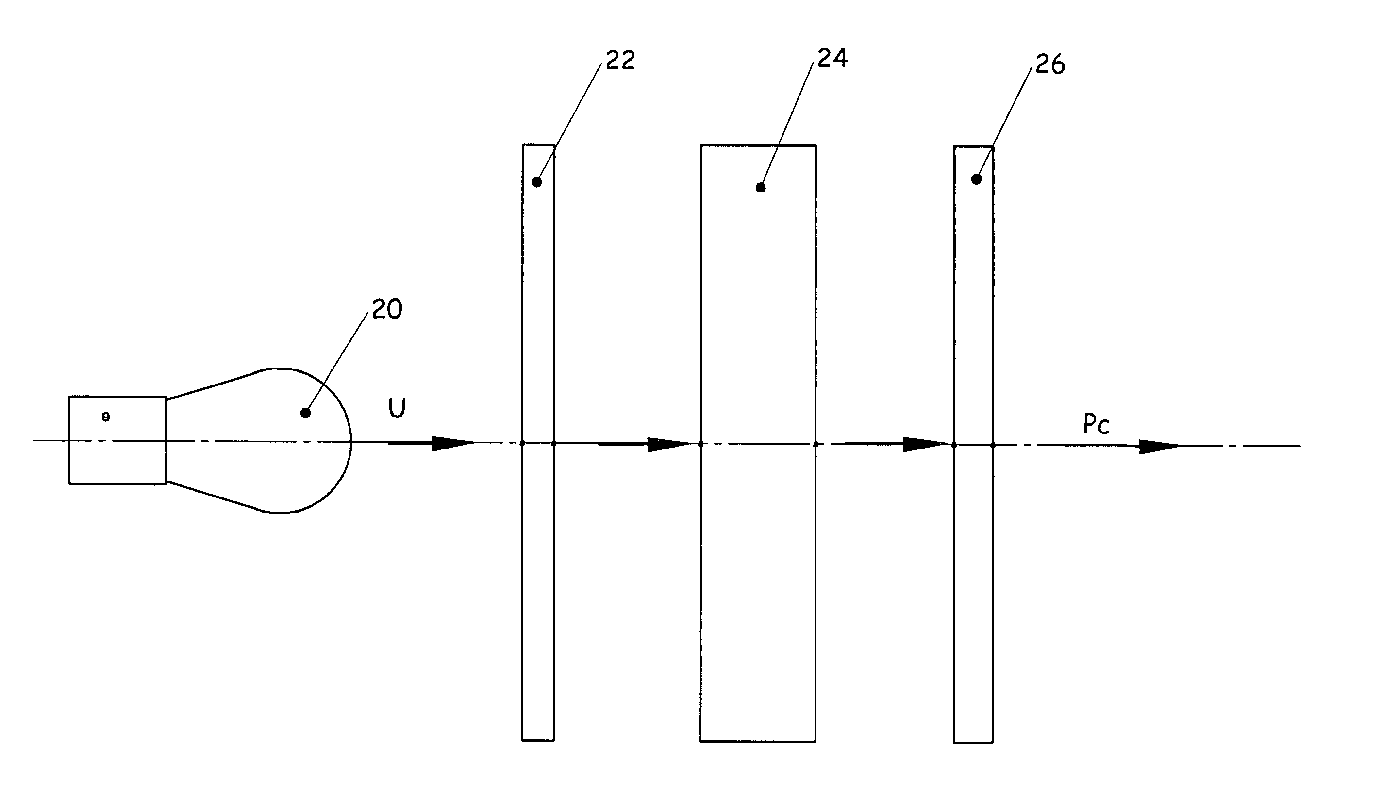
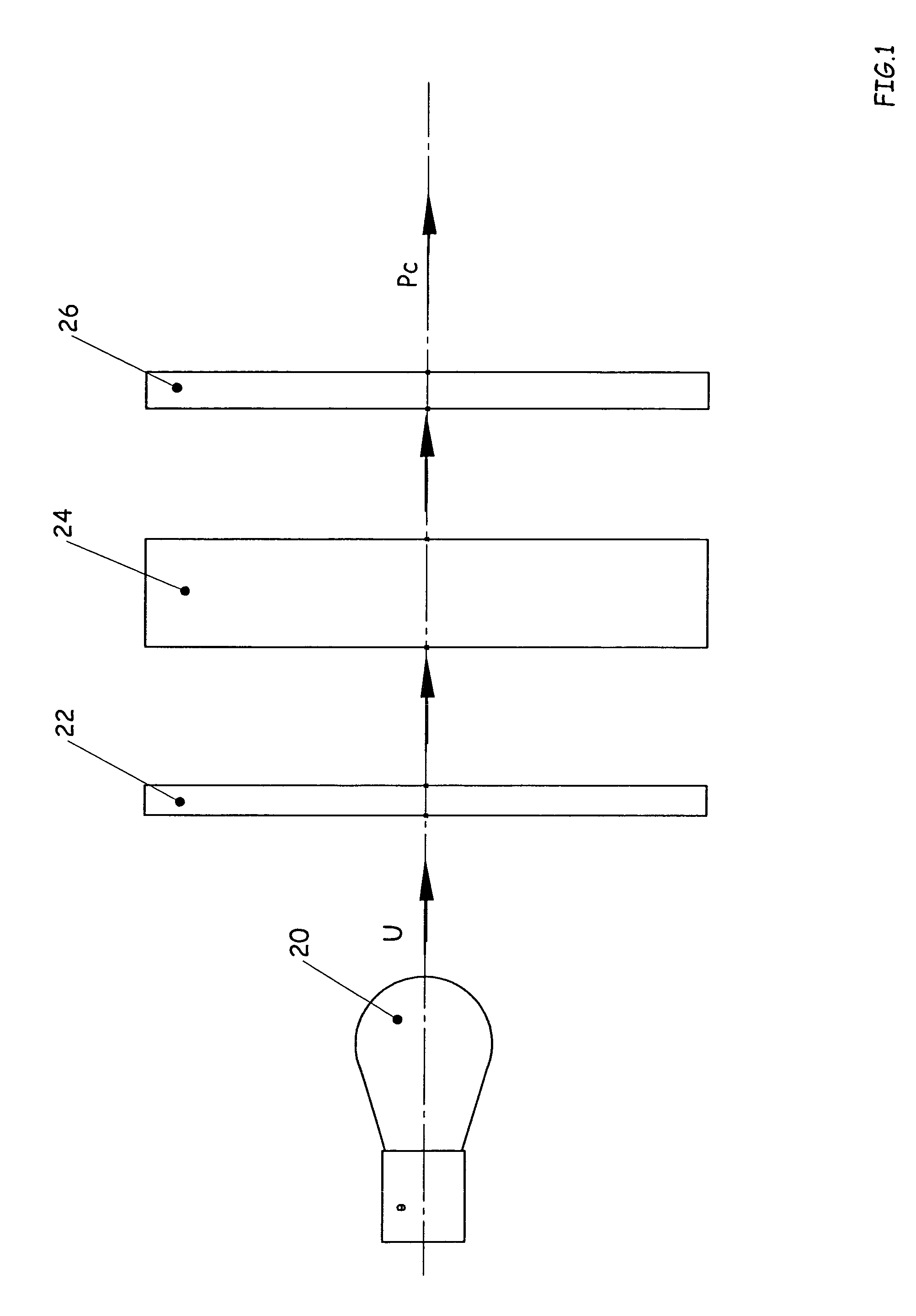
[0024]A diagram of an optically active color filter (hereafter, “color filter”) embodying features of the present invention is shown in FIG. 1. The path of light through the color filter is indicated by arrows. As used herein, the term “front” or “forward” refers to the side of the color filter or component thereof through which light exits while the term “rear”, “back” or “behind” refers to the side of the color filter or component thereof through which light enters. The color filter generally comprises a neutral, linear polarizer 22, an optically active device 24 and an adjustable, neutral, linear polarizer 26 (hereafter, “adjustable polarizer”). As used herein, the term “adjustable linear polarizer” or “adjustable polarizer” refers to a linear polarizer having a polarization axis whose angle of orientation vis-à-vis the axis of incoming light can be adjusted, e.g., mechanically or electrically. Preferably, the linear polarizer 22 is a fixed-position linear polarizer (hereafter, “...


PUM


Abstract

An optically active color filter for controlling the color of light produced by a light source. The color filter includes an optically active device positioned between a linear polarizer and an adjustable position linear polarizer whose orientation can be controlled mechanically or electrically. In a preferred embodiment, the optically active device contains a liquid optically active substance such as high maltose corn syrup. The optically active color filter may be used for controlling the color of a light source such as a stage light or spotlight and in other applications requiring a device for controlling the color of a light source.

Description

PRIORITY CLAIM[0001]This application claims priority from U.S. Provisional Patent Application No. 60 / 411,541 filed on Sep. 18, 2002, the disclosures of which are incorporated herein by reference.FIELD OF INVENTION[0002]This invention generally relates to color filters and, more particularly, to an optically active color filter suitable for use with light sources such as stage lights, spotlights and other similar devices.BACKGROUND OF INVENTION[0003]Typical light sources (e.g., incandescent, fluorescent lights) produce nearly white light. However, color filter devices for controlling the color of lights used for photography, public performances (e.g., stage performances, concerts, sporting events), film-making, architectural design (e.g., wall wash fixtures, spotlights, accent lighting, outdoor lighting), and other similar applications are well known. The most common type of color filter device are dyed gels of various colors that are placed over a white light source (hereafter, “lig...

Claims


Application Information

Patent Timeline
Patent Type & Authority Patents(United States)
IPC IPC(8): G02B27/28G02B5/24
CPCG02B5/24
Inventor BIEVENOUR, TORREY M.LIEBERMAN, LAWRENCE
Owner VISION QUEST LIGHTING
Why Eureka
Try Eureka