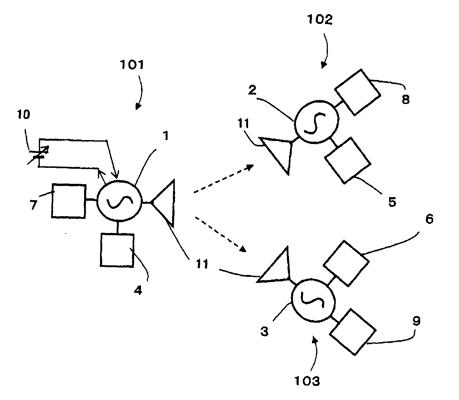
[0023]According to the present invention, the radiating oscillators provided in the respective wireless communication devices are in synchronization with each other in an operating state, by virtue of a pull-in phenomenon. When a signal from one
baseband signal
generating unit is input to a radiating oscillator, the signal changes the frequency of the oscillation signal of the radiating oscillator, and the frequency-modulated oscillation signal is transmitted as an electric wave and is shared in a wireless communication network. At this point, the radiating oscillator functions as a wireless
communication device on the
information transmission side, and the other wireless communication devices function as wireless communication devices on the information reception side. The oscillation frequencies of the radiating oscillators provided in the wireless communication devices on the information reception side vary similarly to the changes in frequency of the radiating oscillator provided in the wireless
communication device on the
information transmission side as a result of synchronization due to the pull-in phenomenon. In this manner, information is transmitted from the information transmission side to the information reception side. In the reception signal detecting units of the wireless communication devices on the information reception side, the information corresponding to the source baseband signal is received based on the variation in frequency. In the wireless communication network system according to the present invention,
signal frequency conversions (up-conversions and down-conversions) are not performed through mixer operations, and the synchronization itself among the radiating oscillators by virtue of a pull-in phenomenon is utilized as an
information sharing means in the network. Accordingly, relatively high-
quality information transmission can be performed with a very simple structure. Furthermore, in a planar radiating oscillator that has a
transistor satisfying the
negative resistance oscillating conditions, it is possible to expect efficiency 20 to 30 times as high as the efficiency obtained in a case where a
Gunn diode is used, and the
power consumption can be reduced. Accordingly, the planner radiating oscillator can provide wireless communication devices as inexpensive components that can operate with batteries, and practical use of wireless communication network systems comprising the wireless communication devices can be expected.
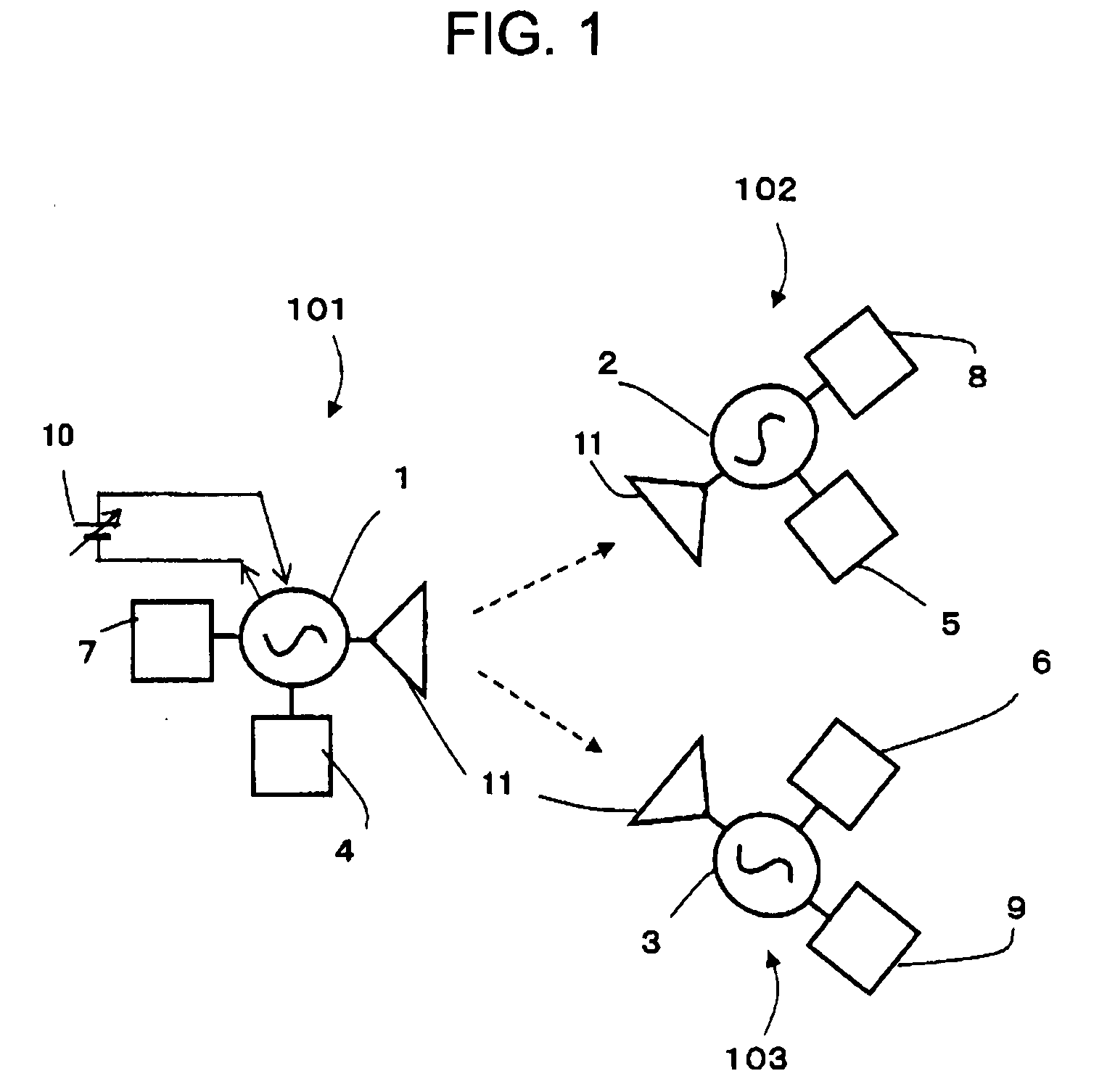
[0024]By appropriately selecting a structure for the radiating oscillators and a radiator structure to be provided in wireless communication devices, output beams can be shaped into one-side direction beams, two-way beams, and multibeams, and those beams are combined to allow a high degree of freedom in designing a network through arrangement of the radiating oscillators. Accordingly, it is possible to provide a technique that has high practicality in the formation of wireless links under complicated installation conditions in many sensor networks, security networks,
communication control networks, and the like. Such a technique can be applied to various fields. In particular, the formation of a wireless communication network of a
millimeter-
wave band with the use of modules having highly-directional beams avoids the problem of interference with other
wireless systems. Such a wireless communication network is suitable for sharing frequencies, and is effective in efficient use of frequency resources.
[0025]In the wireless communication network system, each of the wireless communication devices may have one directional beam or a plurality of directional beams, and have a function to change the direction(s) of the beam(s) and the equivalent isotropic radiated power. In that case, synchronization caused by a pull-in phenomenon can be secured or cancelled in a variable manner in each wireless communication device, and the information transmission
route and the information transmitting direction can be changed in the wireless communication network. Accordingly, a more flexible network can be effectively formed.
[0026]Further, a wireless communication device that does not include both of or one of a baseband signal
generating unit and a reception signal detecting unit may be provided in the wireless communication network, and the wireless communication device may serve as a wireless communication device only having a
relay function, an information transmitting function, or an information receiving function, as needed. In this manner, a wireless communication network system can be formed with a minimum
hardware structure that has no unnecessary parts and is suitable for the intended use.
[0027]Since an address is described for each radiating oscillator, it is easy to identify which part of the wireless communication network system according to the present invention the signal information is transmitted from.
[0028]Furthermore, each of the baseband signal generating units of more than one wireless communication devices may have a function to connect to a signal transmitted from various sensors or another sensor network, and transfer the acquired data of the signal. With this arrangement, it is possible to realize a high-quality sensor network of a superhigh-
frequency band to a millimeter-
wave band that consumes less
electric power and is less expensive.

