Fuel injection nozzle for gas turbine combustor, gas turbine combustor, and gas turbine
a technology of fuel injection nozzle and gas turbine, which is applied in the direction of combustion type, combustion type, combustion using lump and pulverulent fuel, etc., can solve the problems of inability to easily diffuse main fuel, inferior stability of combustion to that of diffusion combustion system, and inability to autoignition premixed gas
- Summary
- Abstract
- Description
- Claims
- Application Information
AI Technical Summary
Benefits of technology
Problems solved by technology
Method used
Image

Examples
first embodiment
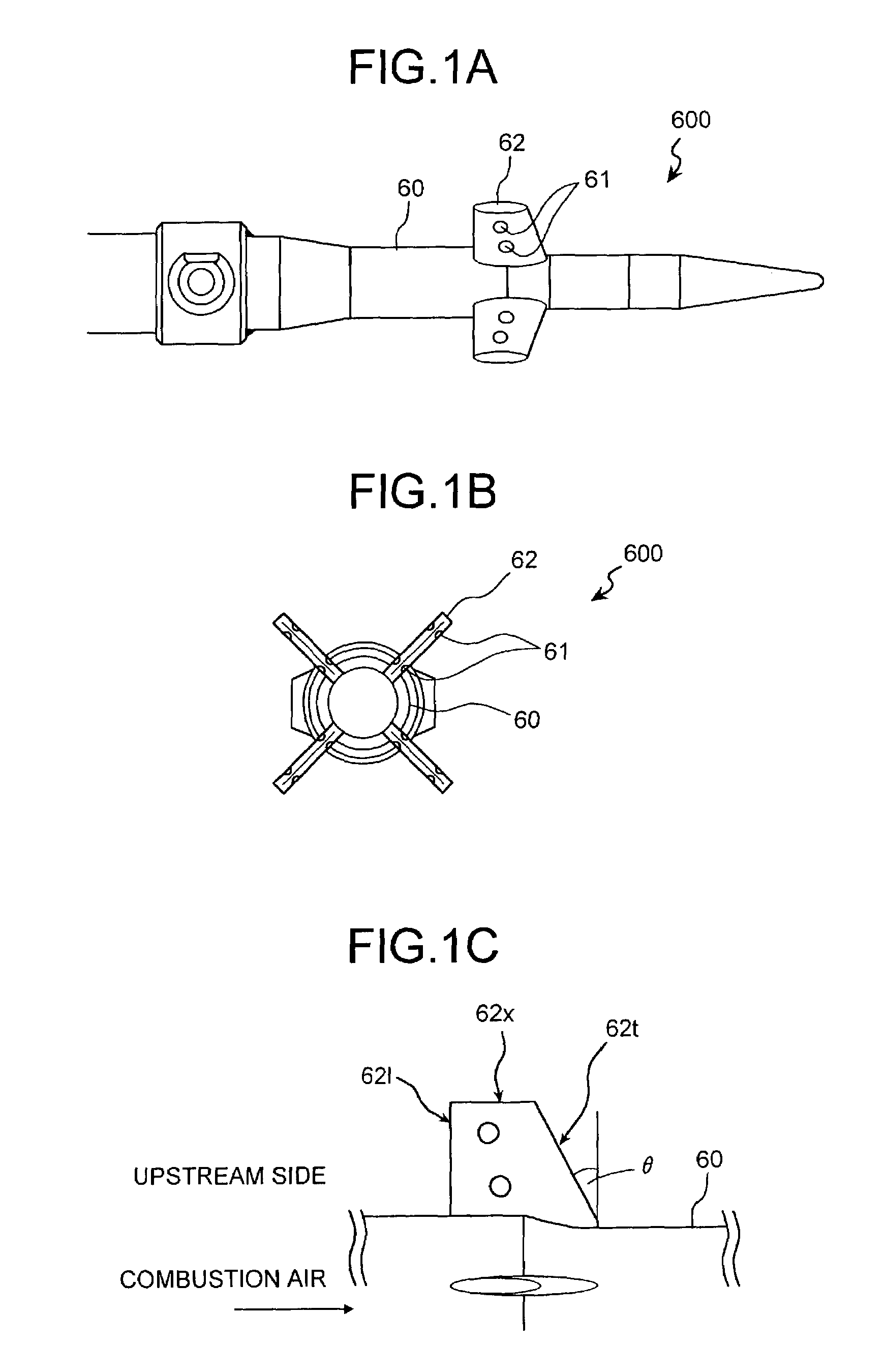
[0044]FIGS. 1A to 1C are diagrams to explain about a fuel injection nozzle for a gas turbine combustor of a first embodiment according to the present invention. As shown in FIGS. 1A to 1C, a fuel injection nozzle 600 according to this embodiment has a cylindrical nozzle body 60. The cylindrical nozzle body 60 has a cavity where fuel flows.
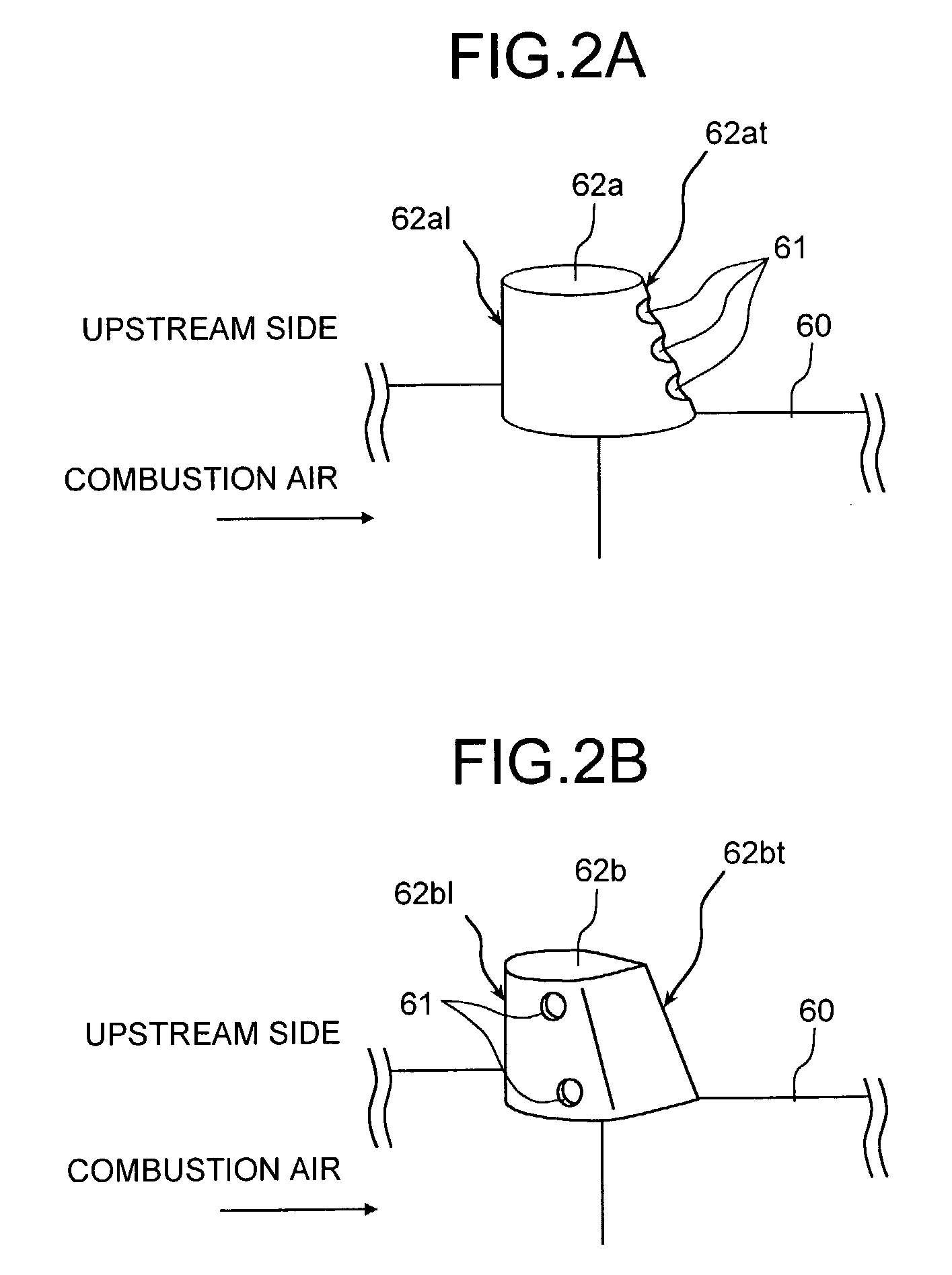
[0045]A plurality of hollow spokes 62, each having an aerofoil cross section, are radially provided around the nozzle body 60 as shown in FIG. 1B. Each hollow spoke 62 has four fuel injection holes 61 in total on both side surfaces, i.e., two fuel injection holes 61 on each side surface, to supply fuel, with a distance from the surface of the nozzle body 60. Each hollow spoke 62 has a cavity where the fuel flows, and the cavity is connected to the cavity of the cylindrical nozzle body 60. The hollow spoke 62 injects the fuel sent to the hollow nozzle body 60, from the fuel injection holes 61 through the inside of the hollow spoke 62. The number of ...
second embodiment
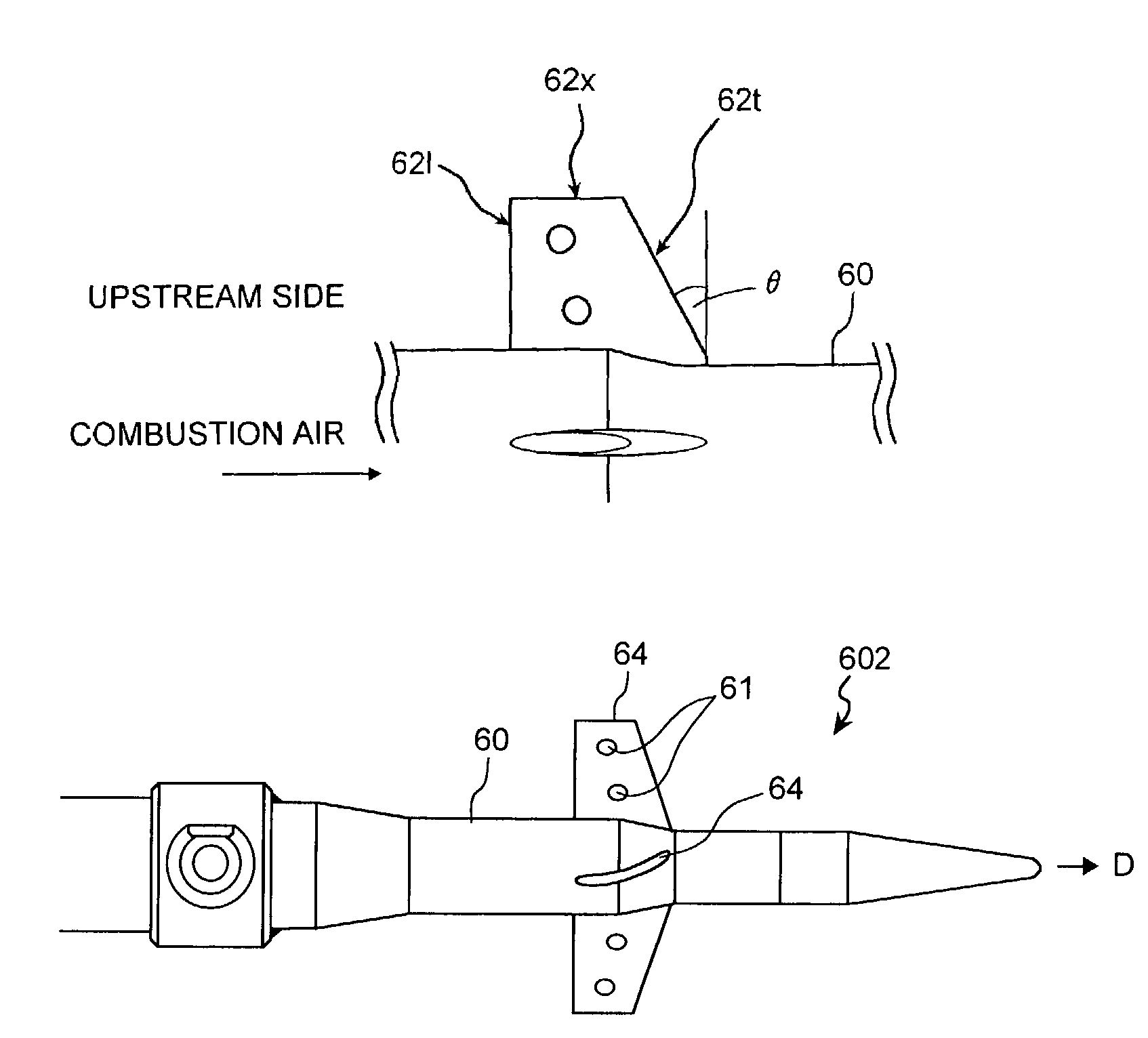
[0055]FIGS. 4A and 4B are diagrams to explain about a fuel injection nozzle for a gas turbine combustor of a second embodiment according to the present invention. As shown in FIGS. 4A and 4B, a fuel injection nozzle 601 according to the present embodiment has hollow spokes 63 inclined toward the flow direction (direction of arrow mark D in FIG. 4A) of the combustion air. With this arrangement, it is possible to give a swirl to the combustion air. Therefore, it is possible to sufficiently mix the fuel with the combustion air at the downstream of the hollow spoke 63.
[0056]As a result, it is possible to suppress the generation of a local high-temperature area, and it becomes possible to further reduce the generation of NOx. Each hollow spoke 63 having an aerofoil cross section does not allow the combustion air to flow far away from the surface of the hollow spoke 63, and the flow of the combustion air is not disturbed at the downstream of the hollow spoke 63. Therefore, it is possible ...
third embodiment
[0058]FIGS. 6A and 6B are diagrams to explain about a fuel injection nozzle for a gas turbine combustor of a third embodiment according to the present invention. As shown in FIGS. 6A and 6B, a fuel injection nozzle 603 according to the present embodiment has hollow spokes 65 fitted to the inner wall of a flame formation nozzle 41. This flame formation nozzle 41 includes a nozzle that mixes fuel with combustion air to form a premixed gas, and forms a premixed flame based on the premixed gas, and a nozzle that injects the fuel to the combustion air to burn the fuel, and forms a diffusion combustion flame. Further, the flame formation nozzle 41 includes a nozzle that injects a mixed gas of pilot fuel and combustion air and a premixed gas, and forms a premixed flame in a second application to be described later.
[0059]As shown in FIGS. 6A and 6B, the fuel injection nozzle 603 that includes four hollow spokes 65, each having an aerofoil cross section, is provided on the inner wall of a fl...
PUM
 Abstract
Description
Claims
Application Information
 - Generate Ideas
- Intellectual Property
- Life Sciences
- Materials
- Tech Scout
- Unparalleled Data Quality
- Higher Quality Content
- 60% Fewer Hallucinations
Browse by: Latest US Patents, China's latest patents, Technical Efficacy Thesaurus, Application Domain, Technology Topic, Popular Technical Reports.
© 2025 PatSnap. All rights reserved.Legal|Privacy policy|Modern Slavery Act Transparency Statement|Sitemap|About US| Contact US: help@patsnap.com