Friction plate for wet type multiplate clutch

a multi-plate clutch and friction plate technology, applied in the direction of fluid-actuated clutches, clutches, non-mechanical actuated clutches, etc., to achieve the effect of improving frictional properties and reducing drag torqu

Active Publication Date: 2007-02-06
NSK WARNER
View PDF13 Cites 21 Cited by
  • Summary
  • Abstract
  • Description
  • Claims
  • Application Information

AI Technical Summary

Benefits of technology

[0010]An object of the present invention is to provide a friction plate for a wet type multiplate clutch which can reduce the drag torque and improve the frictional properties between the friction plate and the separator plate of the clutch.

Problems solved by technology

In addition, in the friction member having oil passages on its surface, it could reduce the drag torque, however, it tends to have high friction coefficient at an initial stage of a frictional engaging, accordingly, there occurs a problem of biting between the friction plate and the separator plate.

Method used


Image

  • Friction plate for wet type multiplate clutch
  • Friction plate for wet type multiplate clutch
  • Friction plate for wet type multiplate clutch

Examples


first embodiment

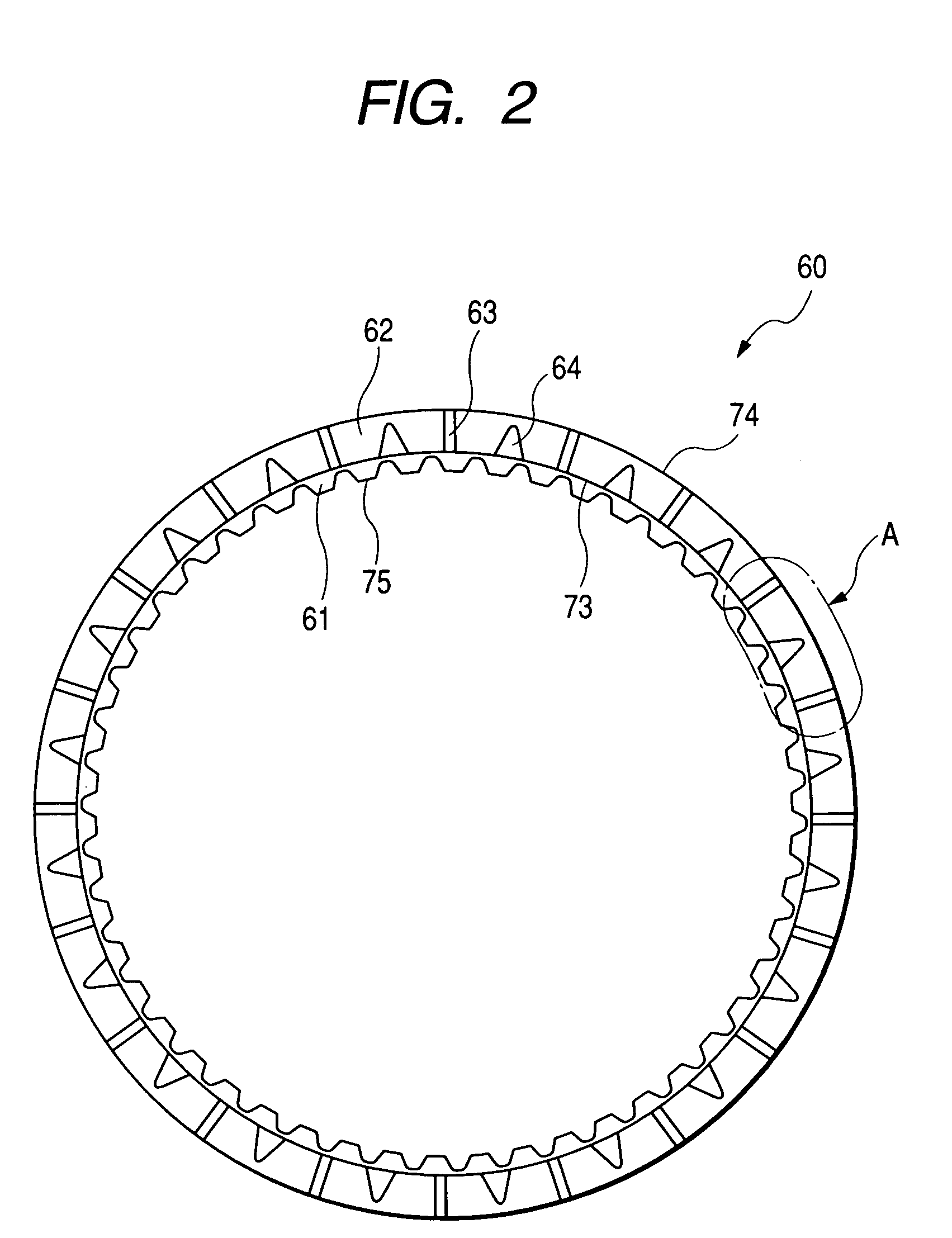
[0051]FIG. 2 is a front view showing a friction plate 60 of the present invention, and FIG. 3 is an enlarged view showing part A in FIG. 2. The friction plate 60 is constituted in such a manner that a friction member 62 is attached on a substantially ring-shaped core plate 61. Spline teeth 75 are formed on an inner peripheral edge of the core plate 61 and spline-engaged with an opposed member to transmit torque from the center shaft to the hub. An oil passage 63 and an oil groove 64 are formed on the friction member 62. The oil passage 63 extends outwardly from an inner peripheral edge 73 to an outer peripheral edge 74 of the friction member 62. The oil groove 64 has an opening end portion which opens to the inner peripheral edge 73 and has a closed end portion 65 on a friction surface of the friction member 62. As shown in FIG. 3 clearly, the oil groove 64 is formed in such a manner that a width 1 at the closed end portion 65 is smaller than a width L at the opening end portion, an...

third embodiment

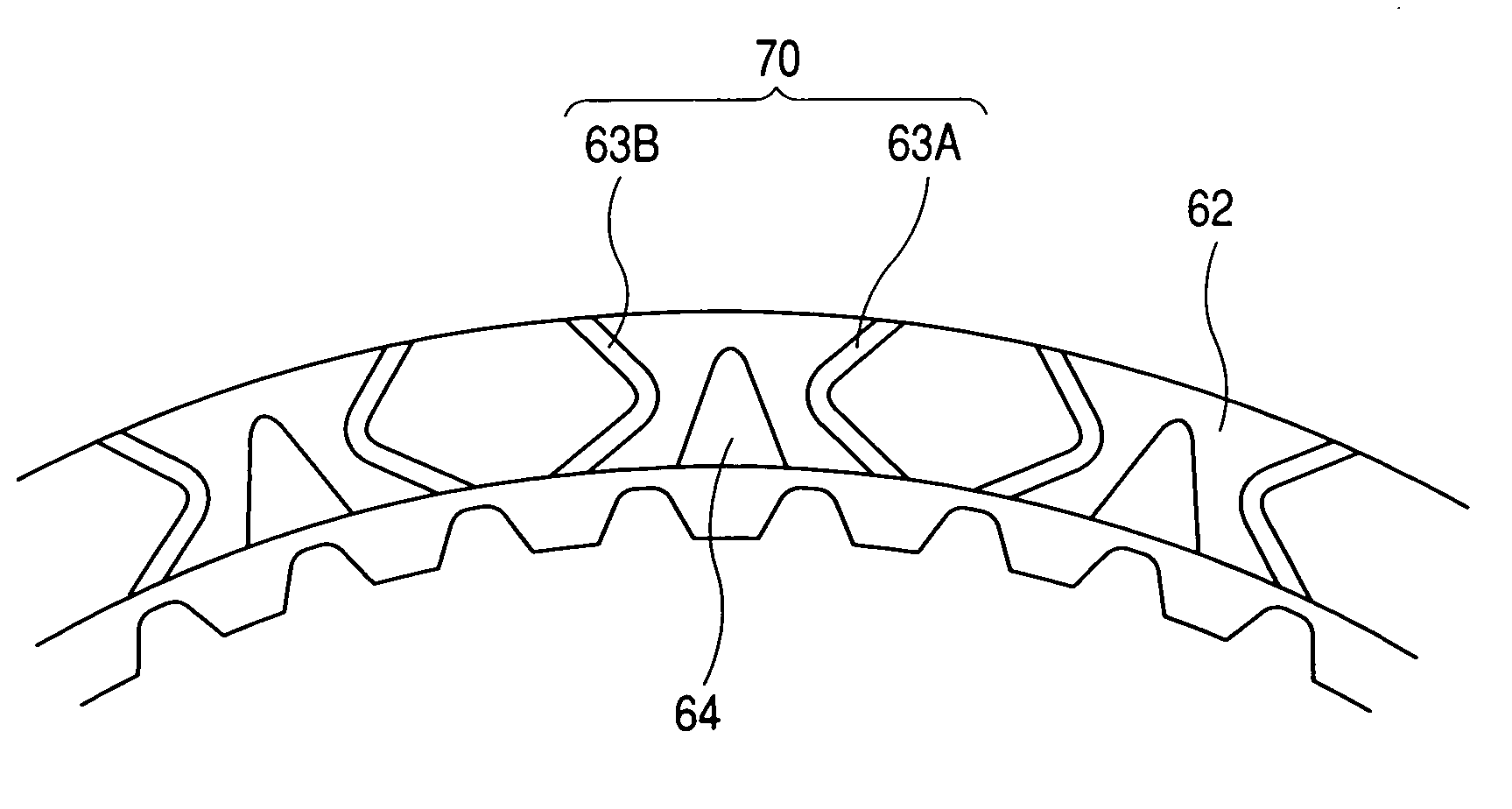
[0054]In the third embodiment as shown in FIG. 5, the friction plate is structured in such a manner that a plurality of pairs of two oil passages are provided on the friction member 62. Each of the pair of two oil passages has a bent portion at a middle portion of the friction surface of the friction member 62, and the two oil passages approach each other fron the inner peripheral edge of the friction member 62 to the bent portion at the middle portion of the friction surface, and then apart from each other from the bent portion at the middle portion to the outer peripheral edge of the friction member 62.

[0055]In other words, in FIG. 5, portions 66A, 66B, which are defined between the inner peripheral edge 73 and the bent portion 68A, 68B at the middle portion of the friction surface of the two oil passages 63A, 63B, are extended so as to approach each other, and portions 67A, 67B which are defined between the bent portions 68A, 68B at the middle portion and the outer peripheral edg...


PUM


Abstract

A friction plate for a wet type multiplate clutch has a substantially ring-shaped core plate and a friction member attached to the core plate. The friction member has a surface which includes a passage formed on a surface of the friction member, the passage extending from an inner peripheral edge of the friction member to an outer peripheral edge of the friction member, and a groove having an opened end which opens to the inner peripheral edge of the friction member and a closed end which is closed at a middle of the surface of the friction member. A width of the groove decreases towards a direction to the outer peripheral edge from the inner peripheral edge of the friction member.

Description

[0001]The present invention claims foreign priority to Japanese patent application no. P.2003-308212, filed on Sep. 1, 2003, the contents of which is incorporated herein by reference.BACKGROUND OF THE INVENTION[0002]1. Field of the Invention[0003]The present invention relates to a friction plate for a wet type multiplate clutch, which can reduce drag torque and improve frictional properties between the friction plate and a separator plate of the clutch.[0004]2. Description of the Related Art[0005]FIG. 1 is a cross-sectional side view showing abasic structure of a wet type multiplate clutch 10. In FIG. 1, the wet type multiplate clutch 10 includes a clutch case 20, a piston 30, a center shaft 40, a separator plate 50 and a friction plate 60. A spline groove 21 is formed on the clutch case 20 and is spline-engaged with the separator plate 50. Also, spline teeth 22 are formed on the clutch case 20 and are spline-engaged with the center shaft 40. The separator plate 50 and the friction ...

Claims


Application Information

Patent Timeline
Patent Type & Authority Patents(United States)
IPC IPC(8): F16D13/74F16D13/62F16D13/64F16D13/72
CPCF16D13/648F16D2069/004F16D25/0638F16D25/123
Inventor KITAHARA, SHUNMIYAZAKI, TOMOYUKIMATSUSHIMA, HIROAKIFUJITA, KAZUYUKI
Owner NSK WARNER
Why Eureka
Try Eureka