Sliding member

a sliding member and dlc film technology, applied in the direction of superimposed coating process, coupling, mechanical apparatus, etc., can solve the problems of insufficient adhesiveness of dlc film with respect to the base material, high internal stress of dlc film, and inability to separate or crack dlc film, etc., to achieve the effect of improving the adhesiveness of dlc film to the base material and increasing the life of the film

Inactive Publication Date: 2010-08-19
JTEKT CORP +1
View PDF5 Cites 20 Cited by
  • Summary
  • Abstract
  • Description
  • Claims
  • Application Information

AI Technical Summary

Benefits of technology

[0009]Accordingly, an object of the present invention is to provide a sliding member capable of increasing the life thereof by further improving adhesiveness of a DLC film to a base material.

Problems solved by technology

If the lubricant runs out, a stick slip (hang-up) may be caused in sliding of the spline portions, to result in noise.
However, the DLC film has extremely high internal stress.
If the DLC film is directly formed on the surface of a base material, therefore, the DLC film may be easily separated or cracked due to low adhesiveness of the DLC film with respect to the base material (particularly a metal substrate).
However, the intermediate layer is constituted of a single film, and hence the adhesiveness of the DLC film with respect to the base material is insufficient.

Method used


Image

  • Sliding member
  • Sliding member
  • Sliding member

Examples


Embodiment Construction

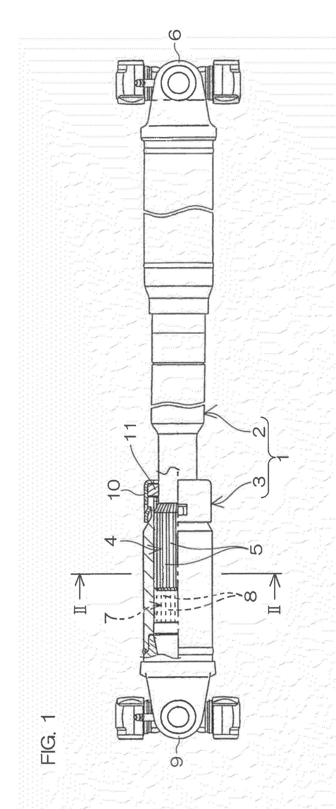
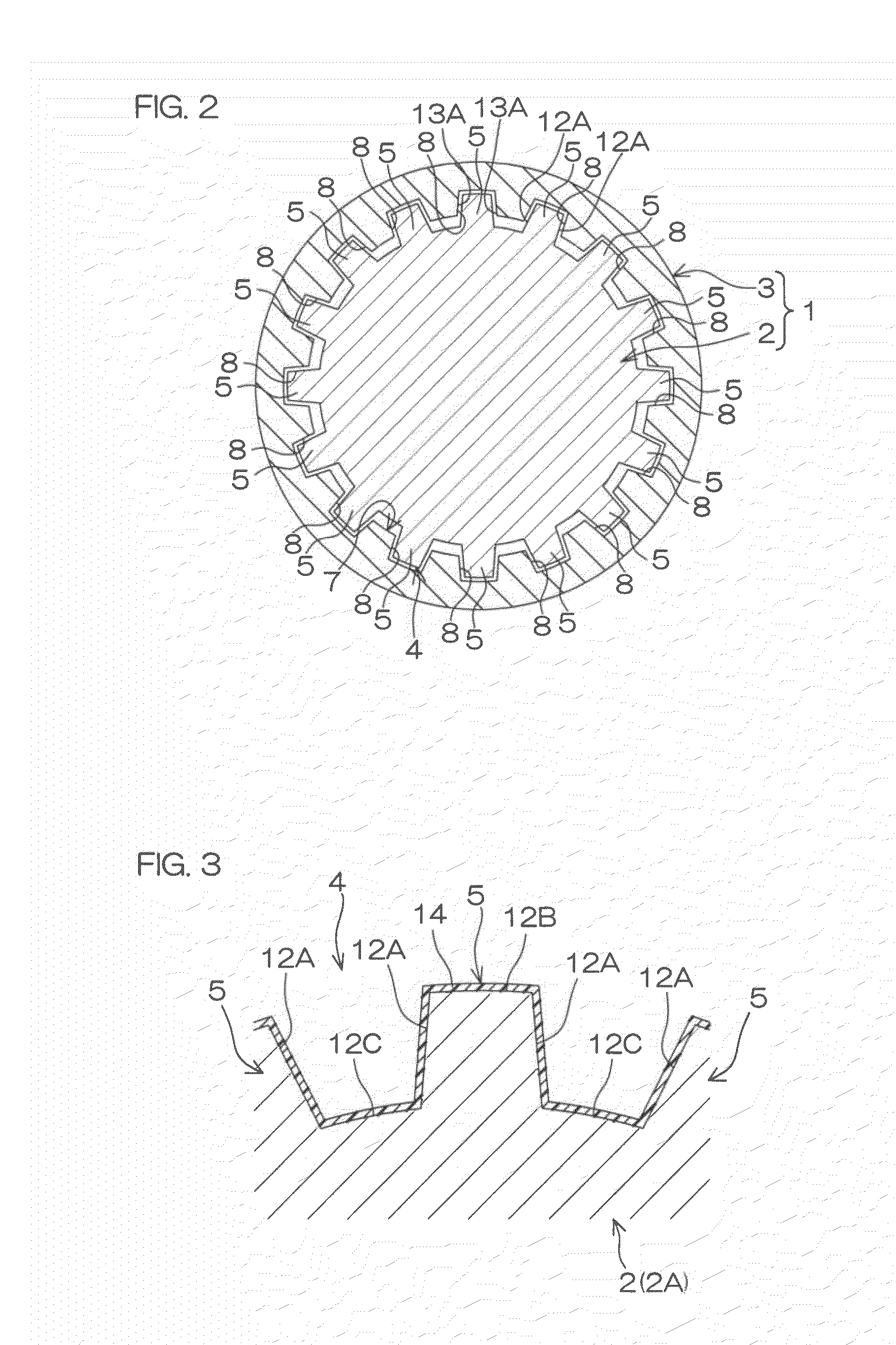
[0025]FIG. 1 is a front elevational view showing a schematic structure of a propeller shaft 1 including a first shaft 2 as a sliding member according to an embodiment of the present invention. FIG. 1 shows the propeller shaft 1 in a partially fragmented manner. FIG. 2 is a sectional view taken along a line II-II in FIG. 1.

[0026]The propeller shaft (a drive shaft) 1 includes the first shaft 2 and a second shaft 3 coupled to the first shaft 2 to be slidable in the axial direction. The first shaft 2 and the second shaft 3 are made of carbon steel (S30C or S45C) respectively. The propeller shaft 1 can be expanded / contracted by axially sliding the second shaft 3 with respect to the first shaft 2.

[0027]An external spline portion 4 is formed on an end portion (the end portion closer to the second shaft 3) of the first shaft 2. The external spline portion 4 includes a large number of keys 5 extending along the axial direction. The keys 5 are provided over the entire periphery of the first s...


PUM

PropertyMeasurementUnit
thicknessaaaaaaaaaa
friction coefficientaaaaaaaaaa
thicknessaaaaaaaaaa

Abstract

A sliding member has a base material whose surface is at least partially covered with a DLC film, wherein an intermediate layer is interposed between the base material and the DLC film, and the intermediate layer has a multilayer structure obtained by stacking a first Cr layer, a CrN layer and a second Cr layer successively from the side closer to the base material.

Description

BACKGROUND OF THE INVENTION[0001]1. Field of the Invention[0002]The present invention relates to a sliding member. The sliding member includes a member such as a spline portion of a propeller shaft (a drive shaft), a cage or a raceway surface of an inner or outer ring of a bearing, or a clutch plate of a friction clutch, for example.[0003]2. Description of Related Art[0004]A vehicle is loaded with a propeller shaft (a drive shaft) for transmitting driving power from the engine to a differential gear. The propeller shaft is formed by coupling two shafts with each other to be expandable / contractible in the axial direction. More specifically, an external spline portion consisting of a plurality of keys along the axial direction and an internal spline portion consisting of a plurality of keyways are formed on the coupled portions of the shafts respectively. The spline portions slidably engage with each other, so that rotational driving force of one of the shafts is transmitted to the ot...

Claims


Application Information

Patent Timeline
Patent Type & Authority Applications(United States)
IPC IPC(8): F16C33/20
CPCC23C16/0272C23C16/0281C23C16/26F16C3/03F16C29/02F16C33/04F16C2206/04F16D2001/103C23C28/322C23C28/325C23C28/34C23C28/343C23C28/347F16D3/06
Inventor SUZUKI, MASAHIROYAMAKAWA, KAZUYOSHISAITO, TOSHIYUKIANDO, JUNJISUZUKI, TOMOOHASHITOMI, HIROYUKIYAMAMOTO, DAIGO
Owner JTEKT CORP
Why Eureka
Try Eureka