Clamp device for pipe or similar component

a technology of curved pipes and clamping devices, which is applied in the direction of lightening support devices, holders, dispensers, etc., can solve the problems of device not being able to accommodate a position change, the device cannot be mounted directly on the car body, and the pipe curved problem

Inactive Publication Date: 2007-02-06
NEWFREY +1
View PDF13 Cites 39 Cited by
  • Summary
  • Abstract
  • Description
  • Claims
  • Application Information

AI Technical Summary

Benefits of technology

[0008]In this configuration, the first clamp is reliably secured to a support such as a car body, long components such as pipes are reliably supported by the second clamp, and transverse movement is possible within the first clamp. As a result, curvature of long components can be accommodated, and the long components can be securely mounted on the support despite the curvature.
[0009]In the clamp device, the movement restricting elements preferably include a plurality of grooves on one of the first cover and the second cover and a protrusion on the other cover for engaging one of the grooves. The protrusion and the grooves engage one another elastically. This allows for movement and transverse positioning of the second clamp with respect to the first clamp, and the proper selection of the position for pipe mounting. In addition, a holder is preferably provided in the first clamp to hold long components.

Problems solved by technology

However, the clamp device cannot be mounted directly on a car body, and curved pipes cannot be mounted on a car body.
The clamp device in Patent Document 2 has a sliding mechanism between a mounting position on a car body and the mounting position of a wire harness, but the device cannot accommodate a position change when the mounting position on the car body and the position where the wire harness is arranged change.
The sliding mechanism in the clamp device in Patent Document 2 does not provide enough fastening strength to keep the long components fastened to the car body.
However, it cannot provide sufficient stud position tolerance when all pipe clamp portions move with respect to stud mounting portions, and the mounting positions do not change when there is curvature in various pipes.

Method used


Image

  • Clamp device for pipe or similar component
  • Clamp device for pipe or similar component
  • Clamp device for pipe or similar component

Examples


Embodiment Construction

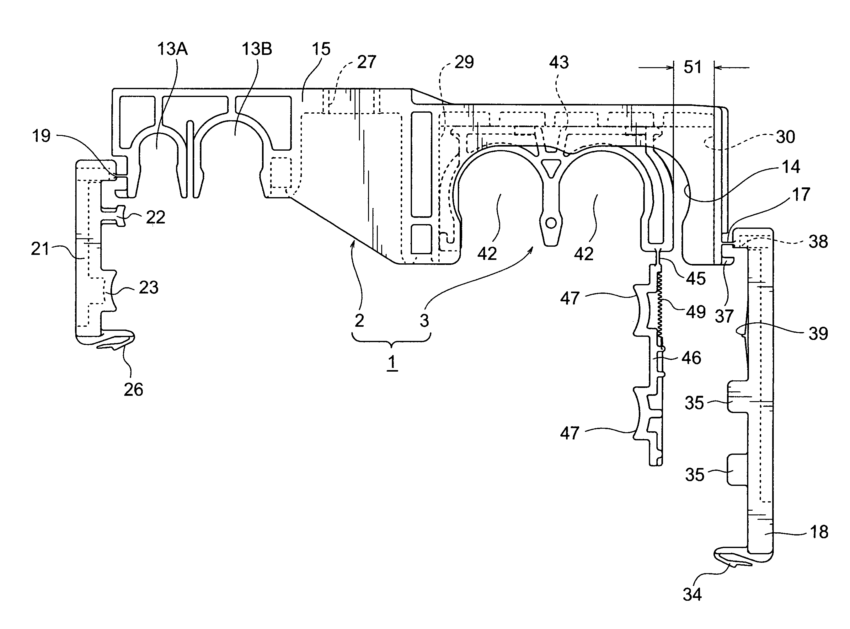
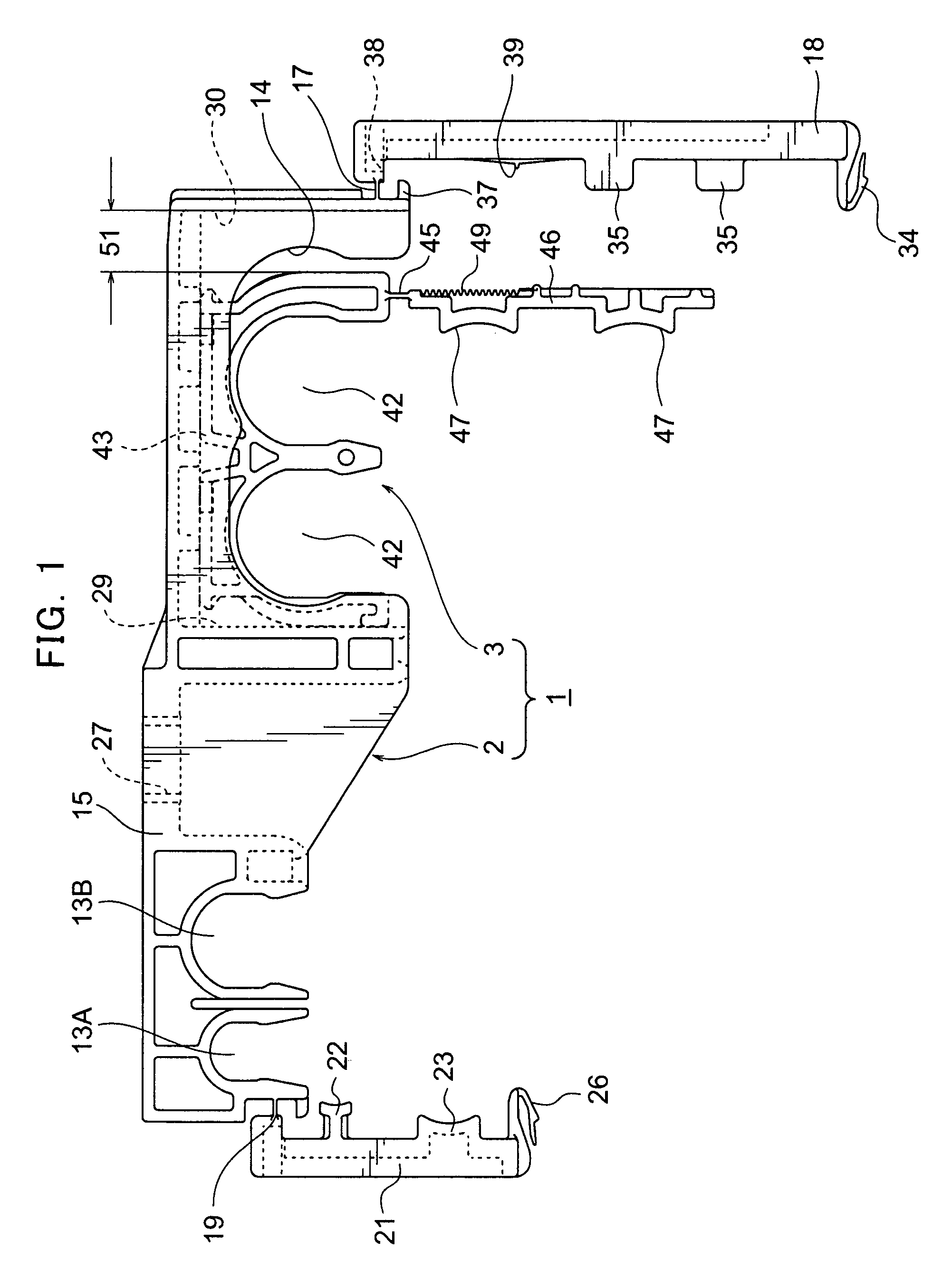
[0020]A non-limiting embodiment of the present invention will now be explained with reference to the drawings. As shown in FIG. 1 and FIG. 2, in the present invention the clamp device 1 for components such as pipes comprises a first clamp 2 and a second clamp 3, preferably forming an integrated plastic product. The first clamp 2 is secured to a support such as the underfloor of an automobile using a stud bolt or normal bolt. The second clamp 3 holds at least one long component such as a heater pipe, brake fluid pipe or wire harness, and is itself held by the first clamp 2.

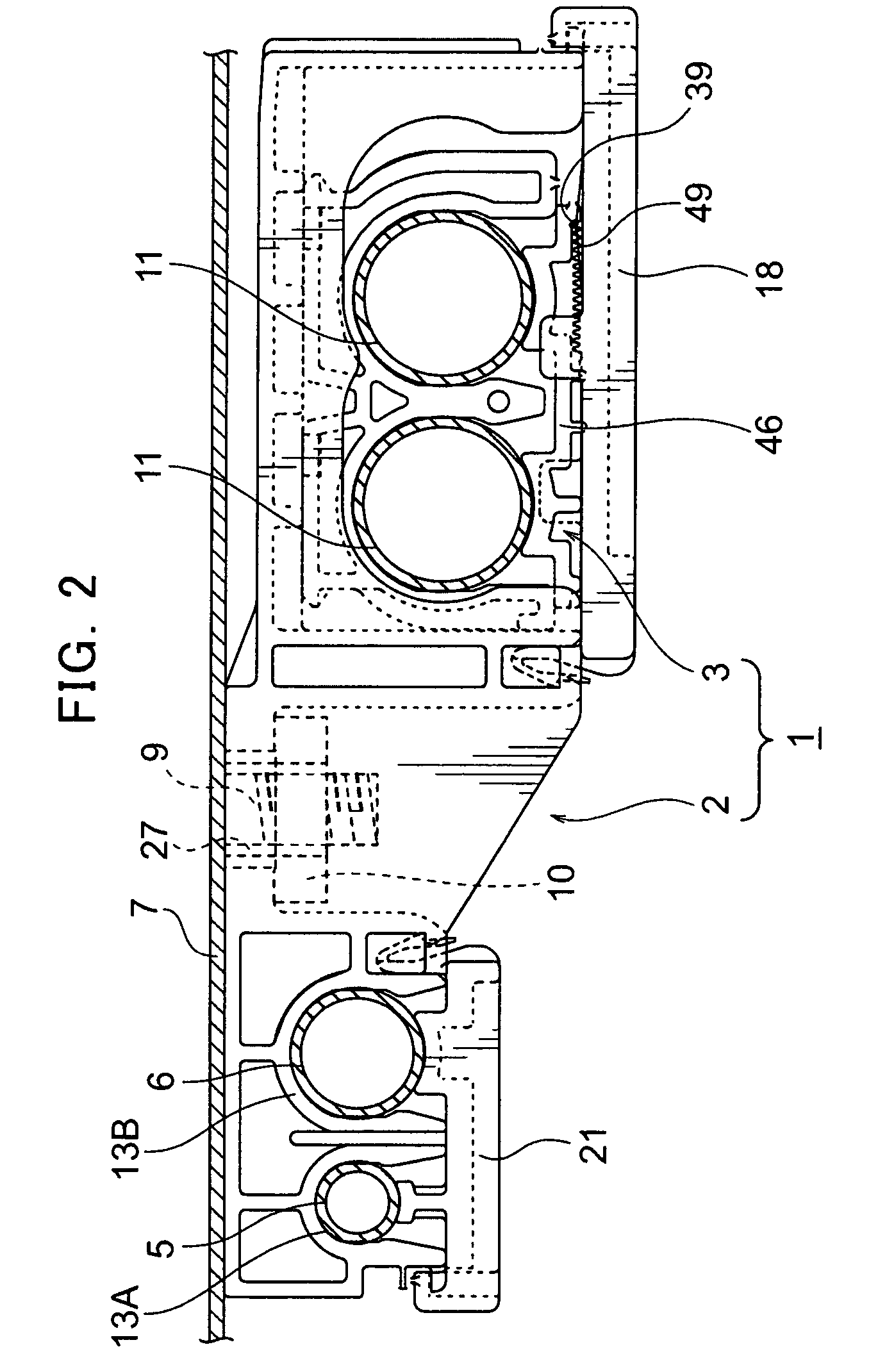
[0021]In one example shown in FIG. 2, the first clamp 2 holds a pipe 5 with a small diameter and a pipe 6 with a slightly larger diameter. The first clamp 2 is mounted on a car body 7 by a nut 10 screwed into a stud bolt 9 fixed to the car body 7. Large diameter pipes 11 such as heater pipes are held by the second clamp 3. The first clamp 2 will be explained below in detail with respect to FIG. 3 through FIG. 6, an...


PUM


Abstract

A clamp device for mounting elongated components such as pipes on a support such as a car body comprises a first clamp to be mounted on the support and a second clamp to be mounted in a recess in the first clamp. The clamp device is constructed to permit limited transverse movement of the second clamp in the recess, to accommodate bending or curving of elongated components held by the second clamp. The first clamp may also hold elongated components.

Description

CROSS-REFERENCE TO RELATED APPLICATION [0001]This application claims the benefit of Japanese Patent Application No. 2004-141927 filed May 12, 2004, incorporated herein by reference.BACKGROUND OF THE INVENTION[0002]The present invention relates to a clamp device for fastening long components such as heater pipes to a support such as the underfloor of an automobile.[0003]Clamp devices for mounting long components, such as heater pipes, brake fluid pipes and fuel pipes, to supports, such as the underfloor in an automobile, are well known. Such elongated components may have a specific length that conforms to a specific mounting location. However, some tolerance is usually allowed within a certain range. If the long components are beyond the allowed tolerance, they can be bent to curve between two mounting positions, but they must be properly mounted even when bent and curved in places.[0004]A clamp is disclosed in Unexamined Utility Model Application Publication No. 56-056976 (Patent Do...

Claims


Application Information

Patent Timeline
Patent Type & Authority Patents(United States)
IPC IPC(8): F16L3/22B23Q3/06B60H1/00F16L3/08
CPCF16L3/2235B60H1/00557
Inventor MIZUKOSHI, SUGURUSHIBUYA, TOMIOTANAKA, YASUOJINNAI, SHUNYAKANBE, MASATO
Owner NEWFREY
Why Eureka
Try Eureka