Mailbox holder

a mailbox holder and mailbox technology, applied in the field of mailbox holders, can solve the problems of ineffective or relatively complicated and expensive mailbox holders, requiring replacement of the entire unit, and other unitary mailbox holders are easily damaged, so as to achieve cost-effective manufacturing

Inactive Publication Date: 2007-02-06
JOHNSON DAN F
View PDF27 Cites 39 Cited by
  • Summary
  • Abstract
  • Description
  • Claims
  • Application Information

AI Technical Summary

Benefits of technology

[0012]The general aim of the present invention is to provide a new and improved mailbox holder suitable for roadside use, the mailbox holder being uniquely adapted for durability and ease of assembly and installation into the ground, and that is cost effective to manufacture.
[0013]A detailed objective of the invention is to provide a mailbox holder constructed from two parts—a lower support with an integral stake for insertion into the ground, and an upper support that is secured to the lower support after installation into the ground, the upper support being adapted to carry the mailbox. This arrangement enables removal and replacement of the upper support without disturbing the lower ground support. This arrangement is further advantageous because a two-part mailbox holder can be typically manufactured and shipped at less cost than manufacture and shipment of a similarly constructed one-piece unit, the lower stake configuration promotes ease of installation into the ground, with no digging or concrete required, the upper support is easily removed for maintenance, transportation or replacement in the event of damage, and replacement of the upper support will be less expensive and easier than replacement of the entire mailbox holder.
[0014]Another detailed objective is to provide a mailbox holder that is of sturdy metal, tubular construction, including bolt-together face-to-face mating flanges between the upper and lower supports, and use of high-strength bolts to prevent the upper support from easily breaking away from the lower support. The heavy duty construction ensures long term durability of the holder. Contrary to certain prior mailbox holders, the mating flanges of the present invention are not intended for ease of breakaway, but rather are intended to resist breakaway from a strike against the upper support, substantially equally in all directions. The tubular design of ground stake with a flange in the form of a heavy duty top plate permits installation with a heavy hammer and results in a more stable unit. And providing a flange that maintains its integrity in the event of a typical strike against the upper holder insures that the post stands firm against unnecessary or accidental breakaway and against malicious damage.

Problems solved by technology

These and other unitary-type mailbox holders are easily damaged and may require replacement of the entire unit if hit by, for example, a motor vehicle, or damaged from mischievous or malicious activity.
Such strike-forgiving mailbox holders tend to be either ineffective, or relatively complicated and expensive, and the play in such holders can compromise unit integrity.
These types of holders also tend to be relatively complicated and expensive, and very few installations ever require such breakaway capability.
This process is, at best, inconvenient, and may be difficult to impossible such as in rocky-ground conditions or during the middle of the winter.
Prior mailbox holders set directly into the ground also tend to lean, raise up, or otherwise shift and move around over a period of time, due to extreme hot-cold temperatures, ground freeze-thaw cycles, wind, rain, and other changing weather conditions.
However, because reuse of the concrete base is generally impossible, and removal of the concrete base can be difficult, a new hole is typically require to replace a damaged mailbox holder.

Method used


Image

  • Mailbox holder
  • Mailbox holder
  • Mailbox holder

Examples


Embodiment Construction

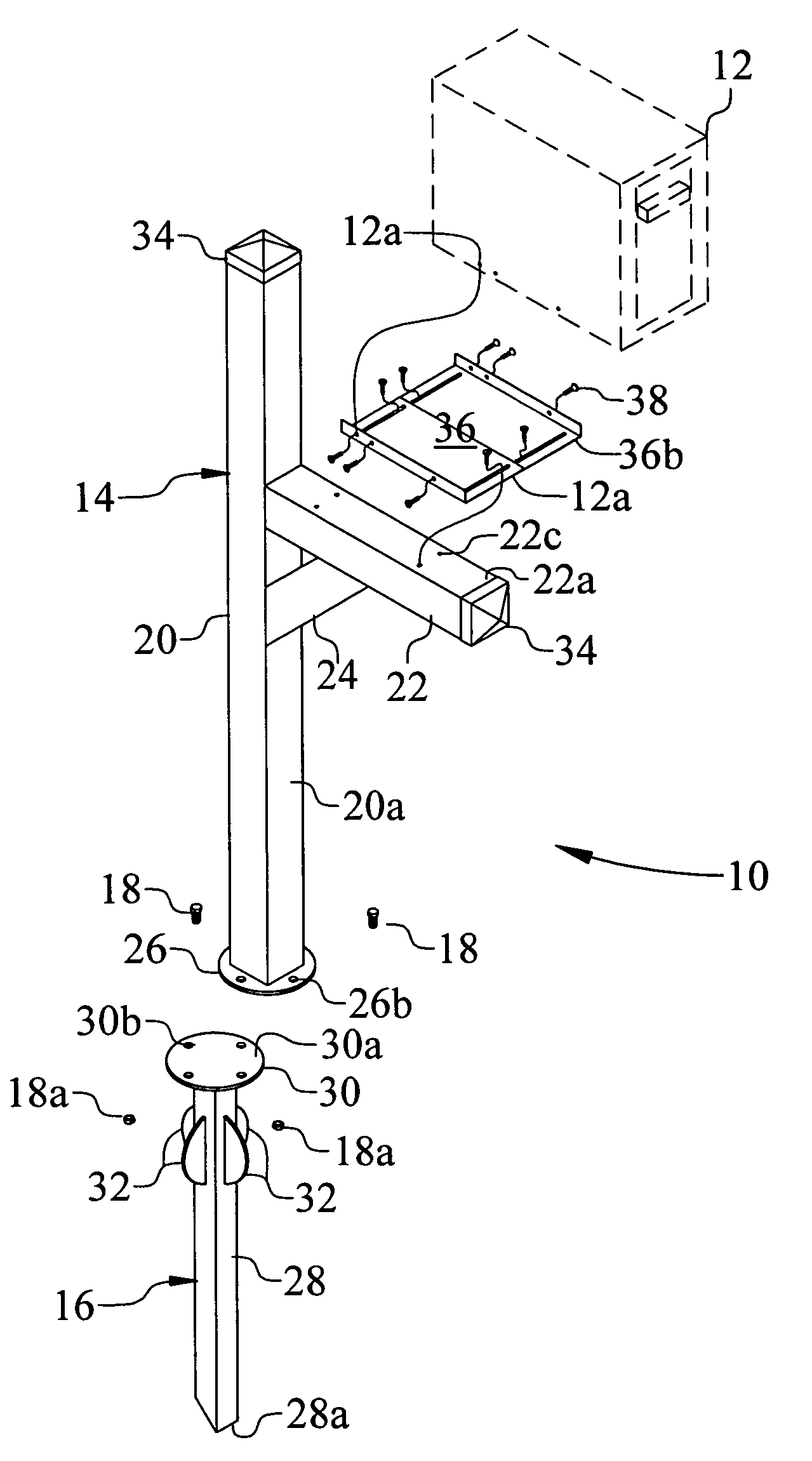
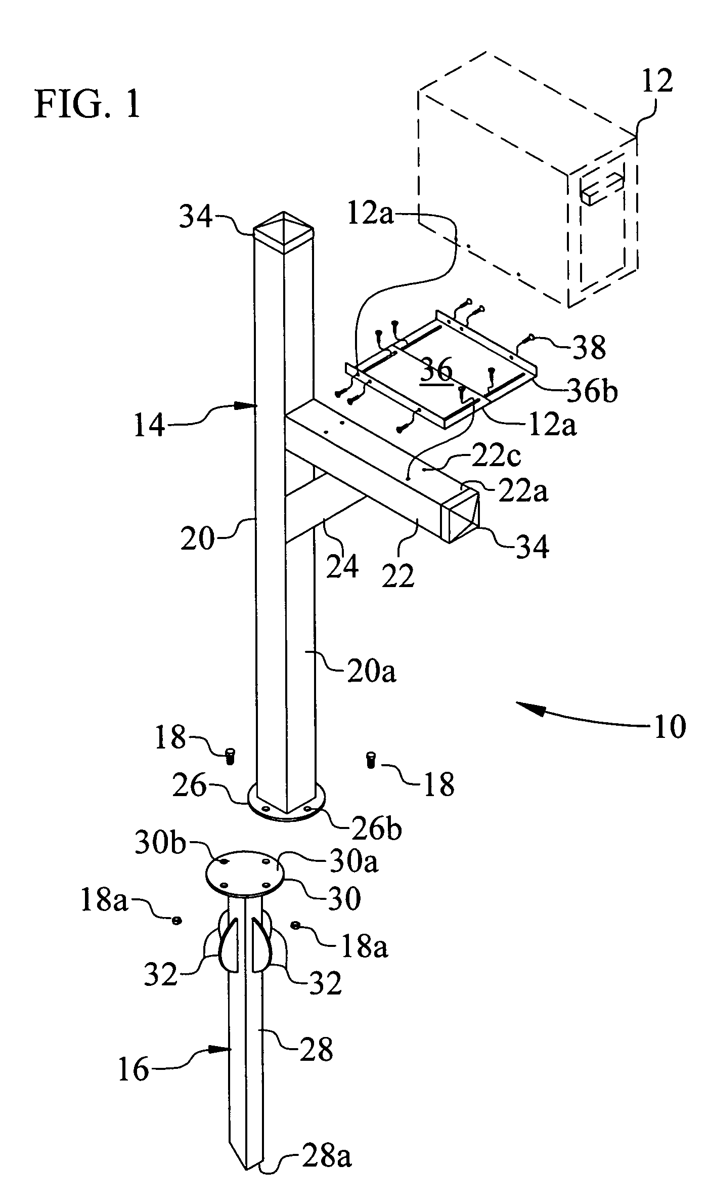
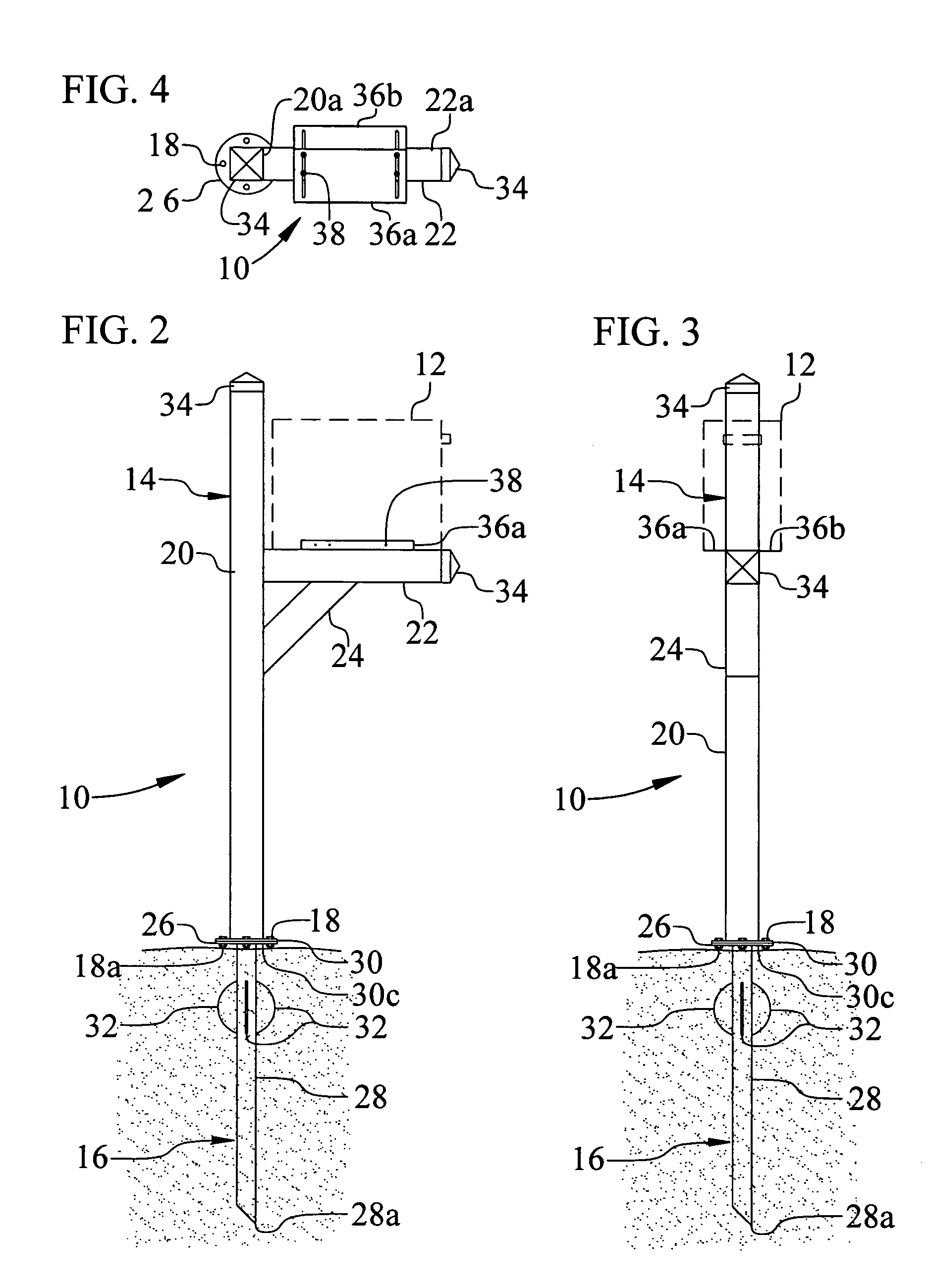
[0039]For purposes of illustration, the present invention is shown in the drawings as mailbox holder 10 (FIGS. 1–4) for holding a mailbox 12 shown in dashed lines.

[0040]The mailbox holder 10 includes an upper mailbox support 14 and a lower ground support 16 that are securely, yet releasably fastened together with high-strength threaded bolts 18 and threaded nuts 18a. The mailbox holder 10 also includes a mailbox attachment bracket 36 that is adjustable for use with mailboxes of different widths.

[0041]The upper mailbox support 14 (FIGS. 5–9) includes a vertical post 20, and a horizontal arm 22 welded (or otherwise rigidly secured) to and extending forwardly from the front side 20a of the upper portion of the vertical post 20 to position the mailbox at a height range above ground such as specified as standard mailbox height by the U.S. postal service. A diagonal support 24 is welded at an angle between the bottom surface 22b of the horizontal arm 22 and the front side 20a of the verti...


PUM


Abstract

A mailbox holder (10) includes an upper mailbox support (14), a lower ground support (16) that is securely fastened to the upper support, and an attachment bracket (36) to which a mailbox (12) is secured. The upper mailbox support includes a vertical post (20), a horizontal arm (22) rigidly welded to the post to carry the mailbox, a diagonal support (24) welded between the horizontal arm and the vertical post, and a circular bolt flange (26) welded to the bottom of the post. The lower ground support includes a vertical stake (28) adapted for direct insertion into the ground, a circular bolt flange (30) welded to the top of the stake for connection to the upper support flange, and radially outwardly extending stabilizers (32) to resist movement of the support in the ground. The bracket is adjustable in width to accommodate mailboxes of different widths.

Description

CROSS-REFERENCES TO RELATED APPLICATIONS[0001]NoneREFERENCE TO SEQUENCE LISTING, TABLE, OR COMPUTER PROGRAM LISTING APPENDIX SUBMITTED ON A COMPACT DISC[0002]Not Applicable.STATEMENT REGARDING FEDERALLY SPONSORED RESEARCH OR DEVELOPMENT[0003]Not Applicable.BACKGROUND OF THE INVENTION[0004]1. Field of Invention[0005]The present invention relates generally to mailbox holders.[0006]More particularly, the invention relates to free-standing mailbox holders of a type suitable to carry a mailbox at a roadside location.[0007]2. Description of Prior Art[0008]Simple, traditional mailbox holders intended for roadside use often consist of a post secured in the ground with a horizontal support arm to which a mailbox is attached. These and other unitary-type mailbox holders are easily damaged and may require replacement of the entire unit if hit by, for example, a motor vehicle, or damaged from mischievous or malicious activity.[0009]Some roadside mailbox holders are arranged to provide limited m...

Claims


Application Information

Patent Timeline
Patent Type & Authority Patents(United States)
IPC IPC(8): A47G23/02
CPCA47G29/1216
Inventor JOHNSON, DAN F.
Owner JOHNSON DAN F
Why Eureka
Try Eureka