Motor vehicle rear seat

a technology for motor vehicles and seats, applied in the direction of vehicle seats, movable seats, dismountable/non-movable seats, etc., can solve the problems of large free space lost somewhere else, separate seat parts, and difficulty in operation, and achieve the effect of simple pivoting of the backrest section

Inactive Publication Date: 2007-02-06
INTIER AUTOMOTIVE SEATING SYST
View PDF11 Cites 23 Cited by
  • Summary
  • Abstract
  • Description
  • Claims
  • Application Information

AI Technical Summary

Benefits of technology

[0017]In an advantageous manner, in a further preferred embodiment of the motor vehicle seat, locking means are respectively provided to prevent the pivoting about the first and second pivot axis. This enables the backrest section to be largely locked in the particular positions.
[0018]In a particularly preferred embodiment of the motor vehicle seat according to the invention, the pivoting device and the backrest section interact in such a manner that the backrest section, when being pivoted from the first position into the second position, can be pivoted merely in one direction of rotation about the second pivot axis from its orientation with the rear side oriented upward. This makes it possible for the operator to pivot the backrest section in a simple manner from the first position into the second position.
[0019]The pivoting device of the motor vehicle seat according to the invention preferably has a first limb, which is fastened to the vehicle floor, a second parallel limb, which is connected in an articulated manner to the backrest section, and a third and fourth limb, which are arranged parallel to each other and are connected in each case firstly to the first limb and secondly to the second limb. Su...

Problems solved by technology

The upholstered seat part of the rear seat causes problems in this regard, since it is in the way of the backrest when the latter is folded forward.
In the above-mentioned rear seats, there is generally the problem that the separate seat parts, after being removed, have to be accommodated loosely somewhere else.
The disadvantage of this construction resides essentially in ...

Method used


Image

  • Motor vehicle rear seat
  • Motor vehicle rear seat
  • Motor vehicle rear seat

Examples


Embodiment Construction

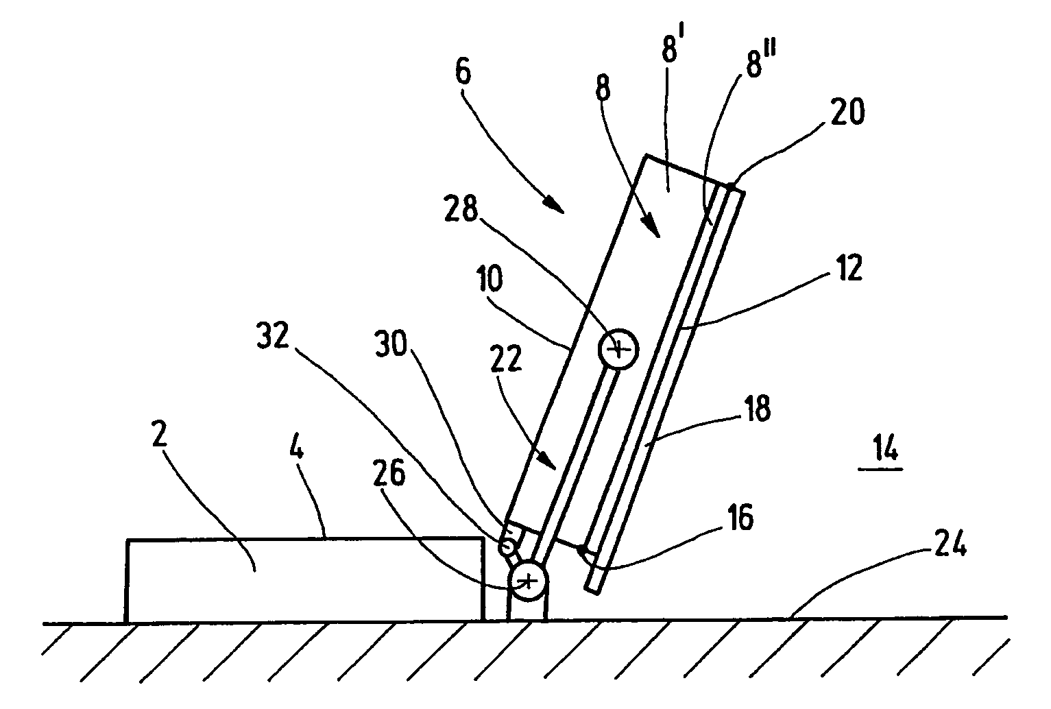
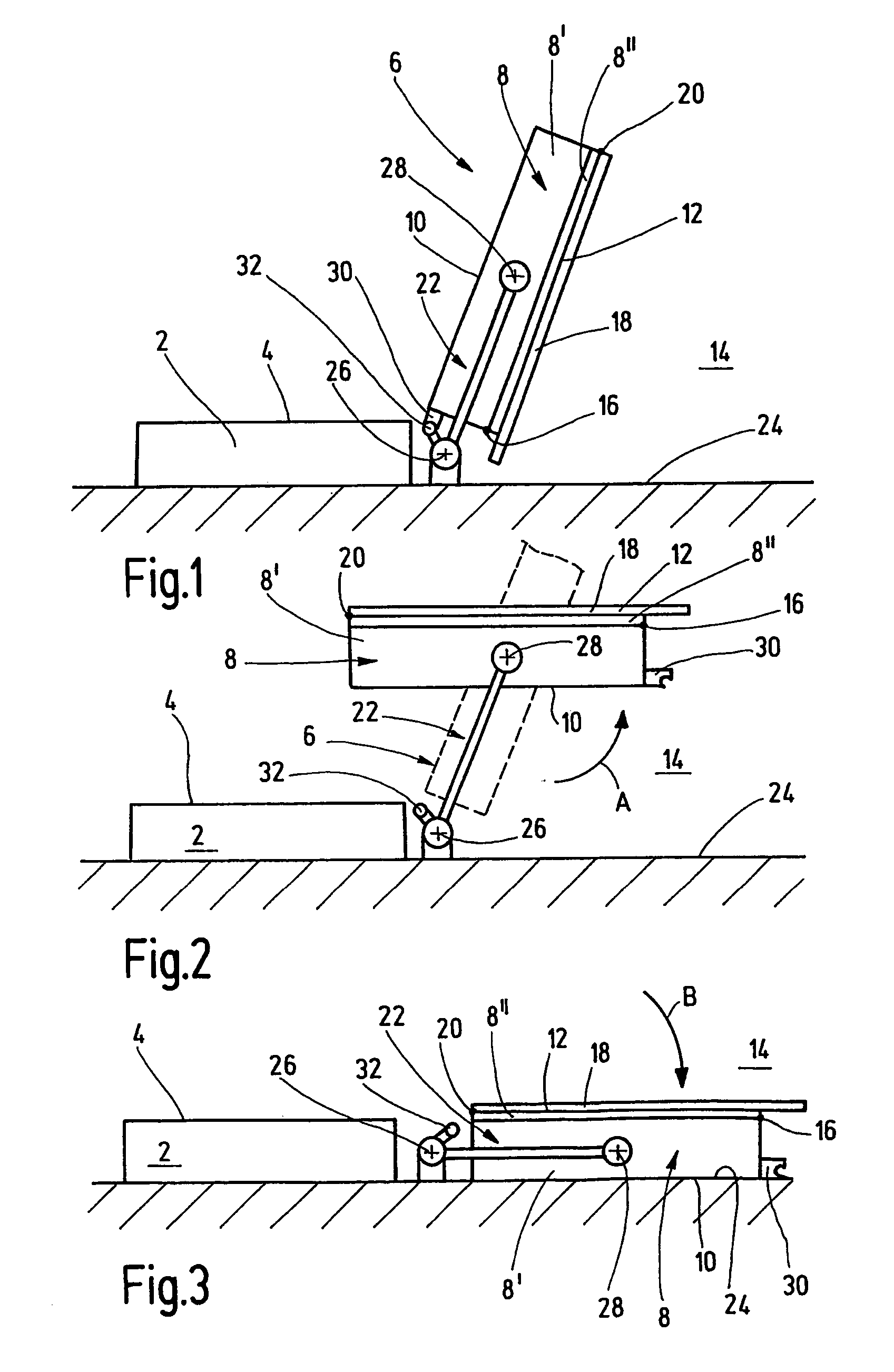
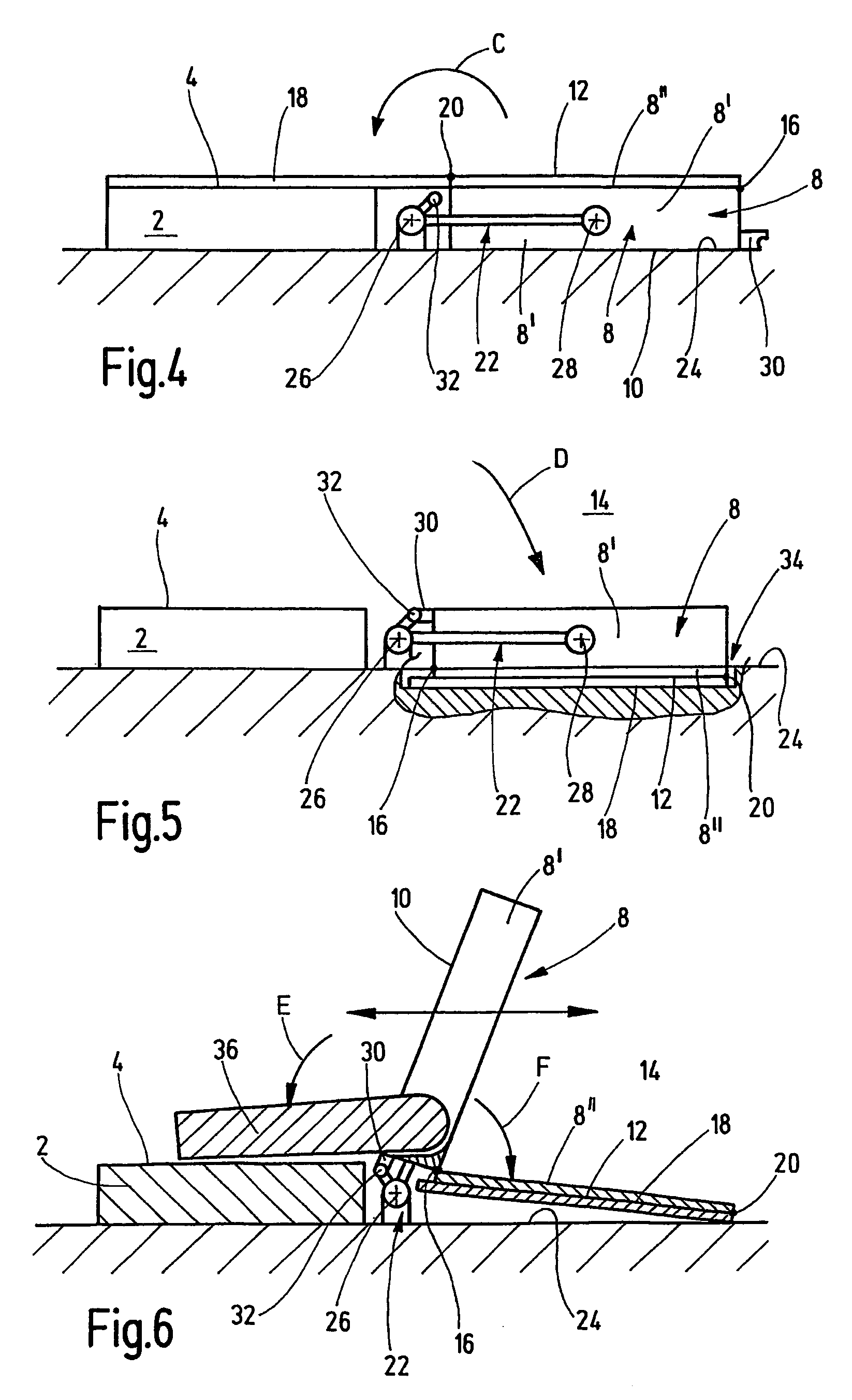
[0034]FIG. 1 shows a side view of the motor vehicle rear seat according to the invention in a diagrammatic illustration. The motor vehicle rear seat has a seat part 2, which is fastened in the motor vehicle and has an upwardly oriented upper side 4 on which a passenger (not illustrated) can sit. Furthermore, a backrest 6 is provided which has at least one backrest section 8, which is shown in FIG. 1 in the normal position, in which the seated passenger can lean against the backrest 6, which is oriented at an angle to the seat part 4. The backrest 6 has a front side 10, which faces the passenger, and a rear side 12, which faces a free space 14 behind the motor vehicle rear seat.

[0035]The backrest section 8 is of sandwich-like construction, i.e. it is composed of upholstery 8′ on the front side and a rear wall 8″ on the rear side. The rear wall 8″ is connected pivotably to the backrest section 8 via a lower, first joint 16 and extends over the entire height of the backrest section 8. ...


PUM


Abstract

The present invention relates to a motor vehicle rear seat with a seat part (2), having an upper side (4), and a seat back (6), having a rear side (12), which faces a clearance behind said motor vehicle rear seat. Said seat back (6) has at least one seat back section (8). According to the invention, said seat back section (8) is designed, such that it can be pivoted from a normal position to a first position, in which the rear side (12) of the seat back section (8) is oriented upwards and, with the upwards-oriented rear side (12), to a second position in the clearance behind the motor vehicle rear seat, such that the upper side (4) of the seat part (2) and the rear side (12) of the seat back section (8) form a loading area. Preferably, a loading plate (18), hinged on said seat back section (8), can be pivoted onto the upper side (4) of the seat part (2) in the second position of the seat back section (8).

Description

BACKGROUND OF THE INVENTION [0001]1. Field of the Invention[0002]The present invention relates to a motor vehicle rear seat pivotal between a first normal position for supporting an occupant in the seat and a second flat position for providing a loading area.[0003]2. Description of the Related Art[0004]Motor vehicle rear seats which offer the option of providing an additional loading area adjoining the luggage compartment situated behind them are known from the prior art. They are used primarily in minibuses, vans, etc., but also in basic passenger vehicles. So that the additionally provided loading area is situated essentially level with the luggage compartment floor, it is necessary for the seat to be constructed to be as flat as possible in its loading position. The upholstered seat part of the rear seat causes problems in this regard, since it is in the way of the backrest when the latter is folded forward.[0005]To solve this problem, rear seats have been developed, in which, be...

Claims


Application Information

Patent Timeline
IPC IPC(8): B60N2/00B60N2/30B60N2/32B60N2/34B60N2/36
CPCB60N2/3031B60N2/309B60N2/34B60N2/36B60N2/32B60N2002/363
Inventor HENNING, WERNER INGMAR
Owner INTIER AUTOMOTIVE SEATING SYST
Why Eureka
Try Eureka