
Contact lens with high-order compensation for non-axisymmetric structure

a compensation and non-axisymmetric technology, applied in the field of contact lenses and other ophthalmic biomedical devices, can solve the problems of reducing imaging performance, reducing imaging performance, and prone to higher-order aberrations in thickness variation, and achieve the effect of improving imaging performan

Active Publication Date: 2007-02-06
BAUSCH & LOMB INC
View PDF3 Cites 63 Cited by
  • Summary
  • Abstract
  • Description
  • Claims
  • Application Information

AI Technical Summary

Benefits of technology

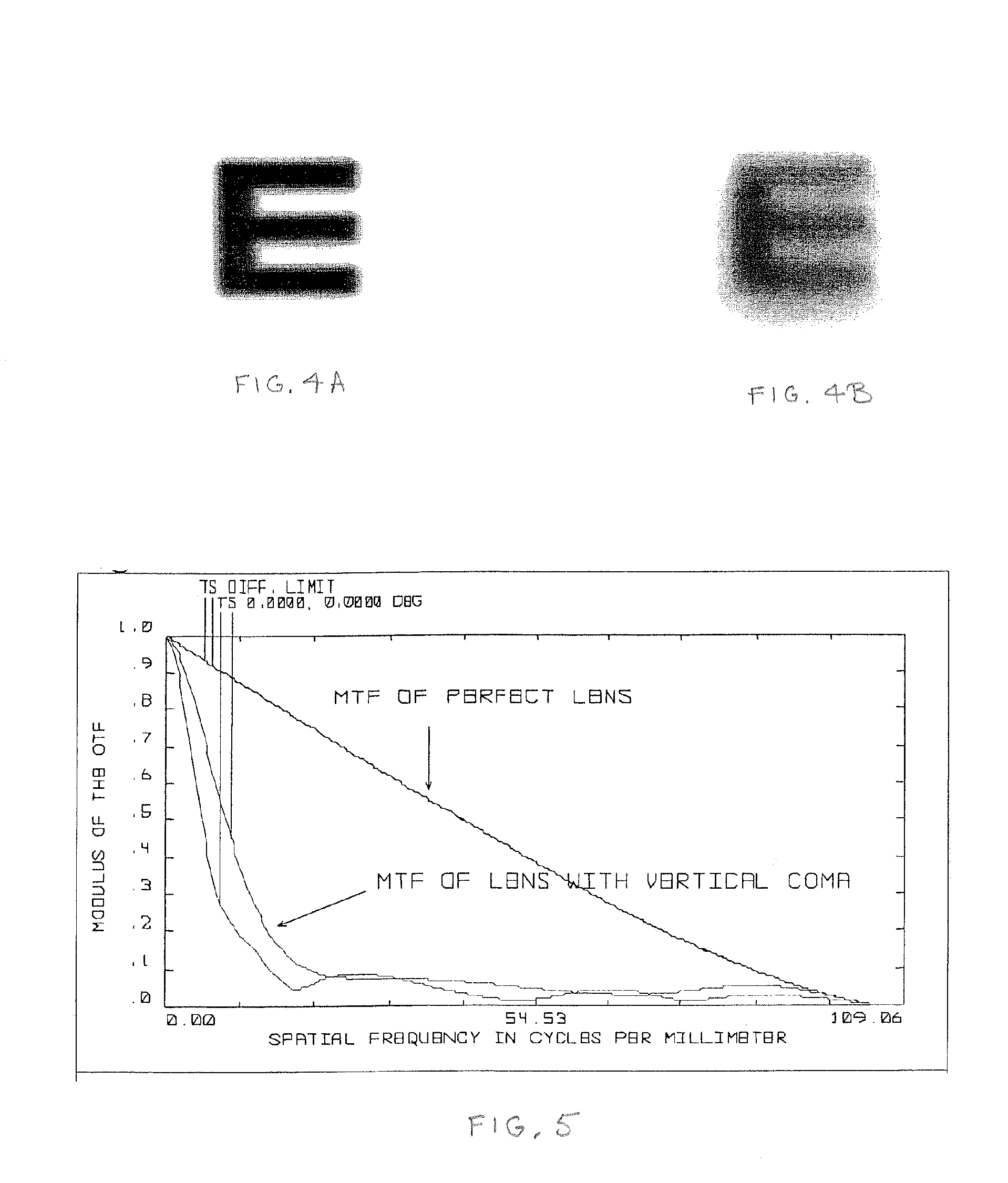
[0017]The structural features can provide for orienting the contact lens bodies on wearers' eyes. For example, the lens bodies can be prism ballasted for orienting the lens bodies on the wearers' eyes, and the wavefront modifiers at least partially compensate for optical aberrations associated with the prism ballasting. For example, the wavefront modifiers can contribute non-axisymmetrical aberrations with respect to optical axes of the wearers' eyes. In particular, the wavefront modifiers can compensate for vertical coma associated with the prism ballasting. The wavefront modifiers can be formed in the anterior or posterior surfaces of the lens bodies and are preferably formed in the anterior surfaces.
[0019]The non-axisymmetric structural feature can contribute a third-order aberration, and the wavefront modifier at least partially compensates for the third-order aberration of the orienting feature. The wavefront modifier also preferably compensates for a plurality of other higher-order aberrations to improve imaging performance. For example, the wavefront modifier can provide corrections for both coma and spherical aberration. Preferably, the wavefront modifier is formed in one of the anterior and posterior surfaces as a non-axisymmetrical surface variation. However, the wavefront modifier can also be formed at least in part by refractive index variations in the focusing optic bodies.

Problems solved by technology

However, in addition to the slight shift in focus position, the directed thickness variation also tends to produce higher-order aberrations, particularly vertical coma, which is a third-order effect.
Such higher-order aberrations can reduce imaging performance, especially under lower light conditions.

Method used


Image

  • Contact lens with high-order compensation for non-axisymmetric structure
  • Contact lens with high-order compensation for non-axisymmetric structure
  • Contact lens with high-order compensation for non-axisymmetric structure

Examples


Embodiment Construction

[0025]Multifocal and toric contact lenses are among the types of contact lenses requiring an associated angular orientation to function as designed. Such angularly sensitive contact lenses are typically formed with some type of ballast to favor a particular orientation of the lenses on wearers' eyes. The ballast sets a neutral angular orientation of the lenses; and angularly sensitive prescriptions, such as the angular orientation of cylindrical axes for fitting astigmatism, are referenced with respect to this neutral orientation.

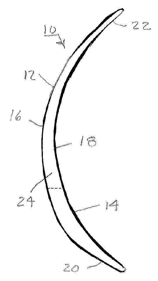
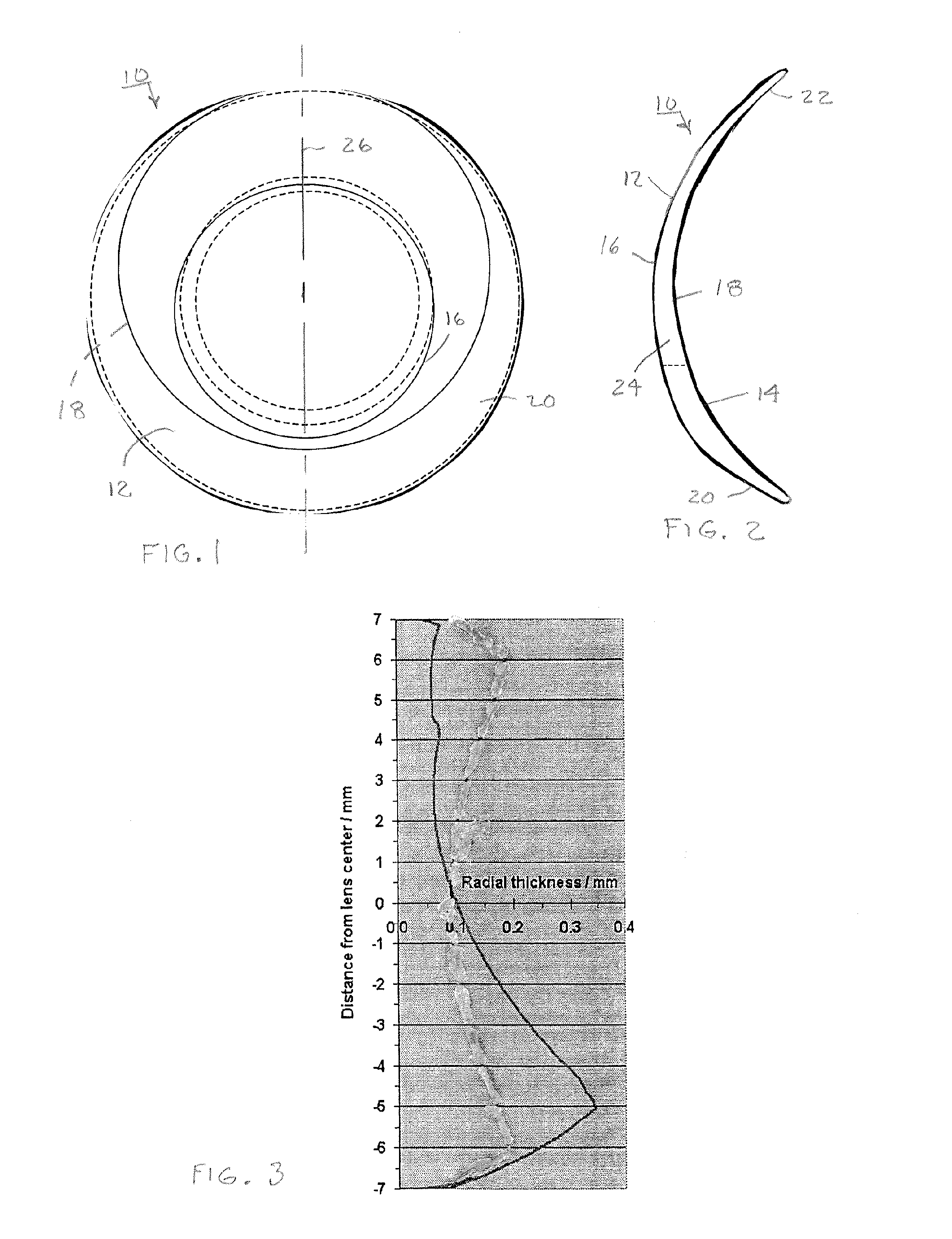
[0026]Typically, the lenses are made with a thickness variation along a so-called ballast axis, which sets the neutral orientation of the lenses. As shown in FIGS. 1 and 2, the thickness variation of a typical toric lens 10 can be achieved by relatively vertically offsetting anterior lens surface 12 with respect to posterior lens surface 14. The offset affects the central zones 16 and 18 of the anterior and posterior lens surfaces 12 and 14 as well as their...


PUM


Abstract

Contact lenses, such as prism ballasted toric lenses, having anterior and posterior surfaces related by way of non-axisymmetric thickness variation can exhibit a third-order aberration, particularly vertical coma. A wavefront modifier, such as an aspheric surface modification, is incorporated into the lenses to at least partially compensate for the wavefront aberration associated with the non-axisymmetric thickness variation. A magnitude of the modifications can be adjusted to set a target value for any remaining wavefront aberration of the lenses based on a population-wide goal.

Description

FIELD OF THE INVENTION[0001]The invention relates to contact lenses and other ophthalmic biomedical devices incorporating non-axisymmetric structural features, such as prism ballasting, and to optical modifications of such lenses and devices compensating for related optical aberrations.BACKGROUND OF THE INVENTION[0002]Optical corrections for conditions such as presbyopia and astigmatism are referenced to particular angular orientations about an optical viewing axis. Stacked focal segments for treating presbyopia have different powers spaced along a common vertical axis. Cylindrical optical corrections for treating astigmatism distinguish optical powers in two orthogonal directions oriented with respect to a common cylindrical axis. To achieve the desired optical corrections, the vertical axis of the presbyopia correction and cylindrical axis of the astigmatism correction must be angularly oriented as intended about the optical viewing axis. Contact lenses for making such corrections...

Claims


Application Information

Patent Timeline
Patent Type & Authority Patents(United States)
IPC IPC(8): G02C7/04
CPCG02C7/028G02C7/04G02C7/048G02C2202/22G02C2202/08
Inventor ALTMANN, GRIFFITH E.COX, IAN G.GREEN, TIMOTHYREINDEL, WILLIAM T.
Owner BAUSCH & LOMB INC
Learn More