

Injection molding valve pin bushing
- Summary
- Abstract
- Description
- Claims
- Application Information
AI Technical Summary
Benefits of technology
Problems solved by technology
Method used
Image

Examples
Embodiment Construction
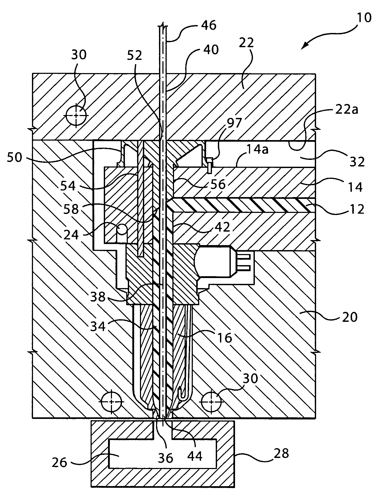
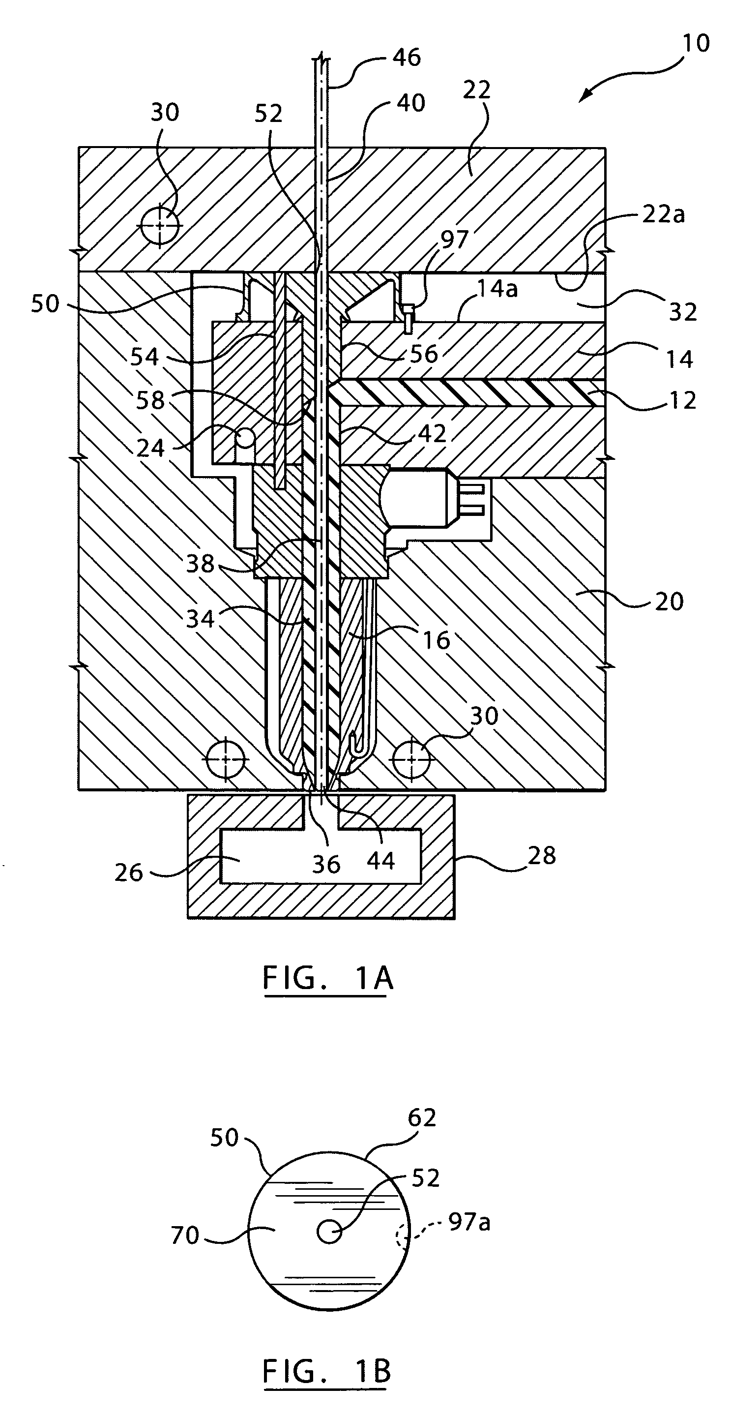
[0023]FIG. 1A shows a portion of a valve gated injection molding apparatus 10 according to an embodiment of the present invention. The injection molding apparatus 10 includes a melt distribution manifold 14 through which a manifold melt passage 12 extends for flow of a pressurized melt stream of moldable material. The manifold 14 is heated by an integral heater 24. The apparatus 10 includes a nozzle 16 to convey the pressurized melt stream through a central nozzle bore, or nozzle melt passage 34, from the manifold melt passage 12 to a cavity 26 in a mold 28. The nozzle 16 is located in a nozzle well in a cavity plate 20 through which cooling conduits 30 are provided for a cooling fluid such as water. The manifold 14 is located between a back plate 22 and the nozzle 16, with an insulating air space 32 provided between a manifold surface 14a of manifold 14 and a back plate surface 22a of back plate 22. Cooling conduits 30 are also provided through the back plate 22. Although only one ...
PUM
| Property | Measurement | Unit |
|---|---|---|
| Melting point | aaaaa | aaaaa |
| Surface area | aaaaa | aaaaa |
| Vacuum | aaaaa | aaaaa |
Abstract
Description
Claims
Application Information