Manifold system for a medical device

a manifold system and medical device technology, applied in the field of medical devices, can solve the problems of prolonging the time needed and complicating the operation performed

Inactive Publication Date: 2007-02-06
MEDLINE INDUSTRIES
View PDF144 Cites 101 Cited by
  • Summary
  • Abstract
  • Description
  • Claims
  • Application Information

AI Technical Summary

Benefits of technology

[0006]In some embodiments, the valve member may be provided as a rotating actuator, a sliding actuator, a pushbutton actuator, or a variety of hybrids and / or combinations of these designs. A number of seals, O-rings, valves, and other elements may also be provided variously to provide a structure for performing the functions of the valve member. Check valves are included in several embodiments for controlling or limiting the direction of fluid flow, for example, to prevent fluid from back flowing to a contrast medium source.

Problems solved by technology

The process of using such manifolds complicates the operations performed, extends the time needed for an operation, and can lead to mistakes.

Method used


Image

  • Manifold system for a medical device
  • Manifold system for a medical device
  • Manifold system for a medical device

Examples


Embodiment Construction

[0030]The following detailed description should be read with reference to the drawings. The drawings, which are not necessarily to scale, depict illustrative embodiments and are not intended to limit the scope of the invention.

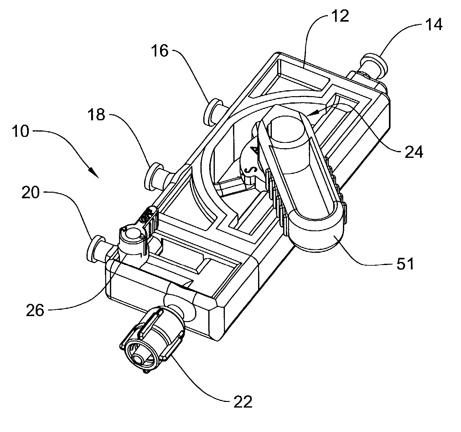
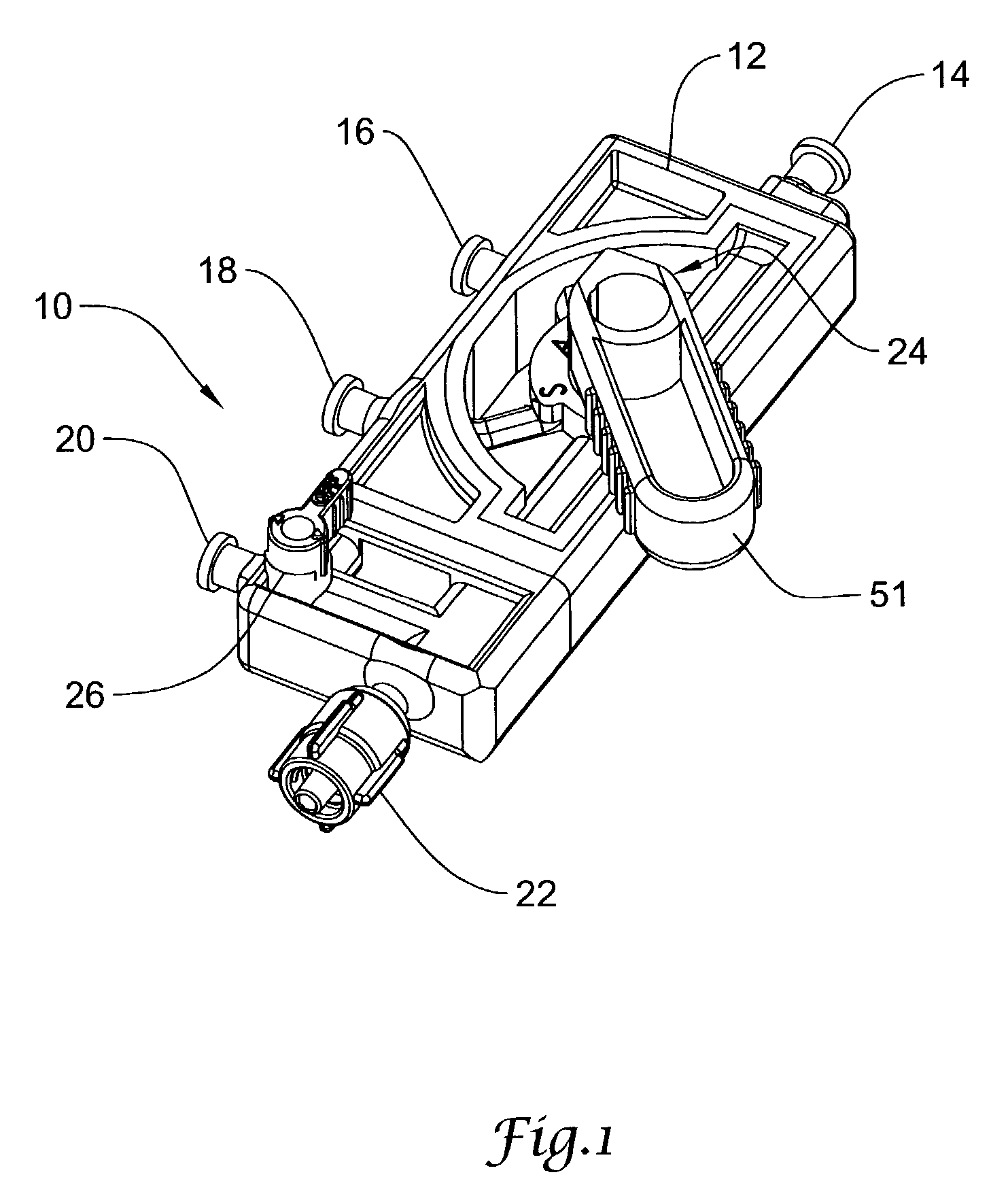
[0031]While the following detailed description is written with reference to a catheter port (e.g., catheter port 22 described in FIG. 1), it should be understood that the term catheter port is used in its most general sense. For example, where a multi-lumen catheter is used, a short coupling piece may couple a “catheter port” to a Luer valve on the proximal end of a Y or other connector placed to allow separate access to the several lumens of a multi–lumen catheter. An introducer sheath or other sheath, cannula, endoscope or any other single or multi-lumen medical device adapted for at least partial insertion into a patient by any vascular or non-vascular route may be coupled directly or indirectly to the present devices via a “catheter port.”

[0032]Any of the ...


PUM


Abstract

A number of devices are illustrated for providing a manifold that can simply and selectively couple a number of different therapeutic and diagnostic elements to a catheter or other medical device. Some examples include devices having sliding actuators, rotary actuators, button actuators, or combinations thereof, for easily changing the valve scheme and fluid pathways within a manifold.

Description

CROSS REFERENCE TO RELATED APPLICATIONS[0001]This application is a continuation-in-part of U.S. patent application Ser. No. 10 / 263,018, filed Oct. 2, 2002 now U.S. Pat. No. 6,918,893; which claims benefit of U.S. Provisional Application No. 60 / 326,941, filed Oct. 4, 2001, the entire disclosure of which is hereby incorporated by reference. This application is also a continuation-in-part of U.S. patent application Ser. No. 10 / 278,663, filed Oct. 23, 2002, now U.S. Pat. No. 6,976,974 the entire disclosure of which is hereby incorporated by reference.FIELD OF THE INVENTION[0002]The invention is related to the area of medical devices. More particularly, the invention is related to manifolds for coupling fluid and pressure / suction sources to a medical device such as a catheter or cannula.BACKGROUND OF THE INVENTION[0003]Manifolds for use with catheters and other medical devices are used for several different functions. Some such manifolds couple more than one fluid source to a catheter, a...

Claims


Application Information

Patent Timeline
Patent Type & Authority Patents(United States)
IPC IPC(8): A61M1/00A61M5/00F16K11/07F16K11/074A61M5/168A61M39/00A61M39/22
CPCA61M39/223A61M5/16827A61M2039/226Y10T137/86823Y10T137/86638
Inventor DIAMOND, SCOTT A.HART, COLIN P.MITCHELL, JAMESDEYETTE, JR., THOMASGARLAPOW, RICHARD M.VAN DIVER, MARK H.WETHERBEE, WILLIAM A.
Owner MEDLINE INDUSTRIES
Why Eureka
Try Eureka