Method and apparatus for driving and controlling on-vehicle loads

a technology for driving and controlling electrical on-vehicle loads, applied in the direction of ac network voltage adjustment, electric devices, transportation and packaging, etc., can solve the problems of increasing the total power consumption remarkably, affecting the operation performance of the vehicle, and limiting the amount of power available, so as to reduce the undesirable influence and reduce the operation performance of the remaining loads.

Active Publication Date: 2007-02-06
DENSO CORP
View PDF23 Cites 91 Cited by
  • Summary
  • Abstract
  • Description
  • Claims
  • Application Information

AI Technical Summary

Benefits of technology

[0010]The present invention has been made with due consideration to the foregoing difficulty, and a first object of the present invention is to provide a method and apparatus for driving and controlling plural on-vehicle electri...

Problems solved by technology

In recent years, the types of electrical loads (hereinafter, simply referred to as loads) mounted on vehicles, such as automobiles, and the total power consumption has been increased remarkably.
When considering the current situations, however, problems attributable to vehicle mounting performance and manufacturing cost pose a limitation to an amount of power available from the power supplies, such as on-vehicle generator and batteries.
Therefore, there is a possibility that a peak of power consumption that las...

Method used


Image

  • Method and apparatus for driving and controlling on-vehicle loads
  • Method and apparatus for driving and controlling on-vehicle loads
  • Method and apparatus for driving and controlling on-vehicle loads

Examples


first embodiment

[0064](First Embodiment)

[0065]An on-vehicle load driving and controlling system according to a first embodiment of the present invention will now be described.

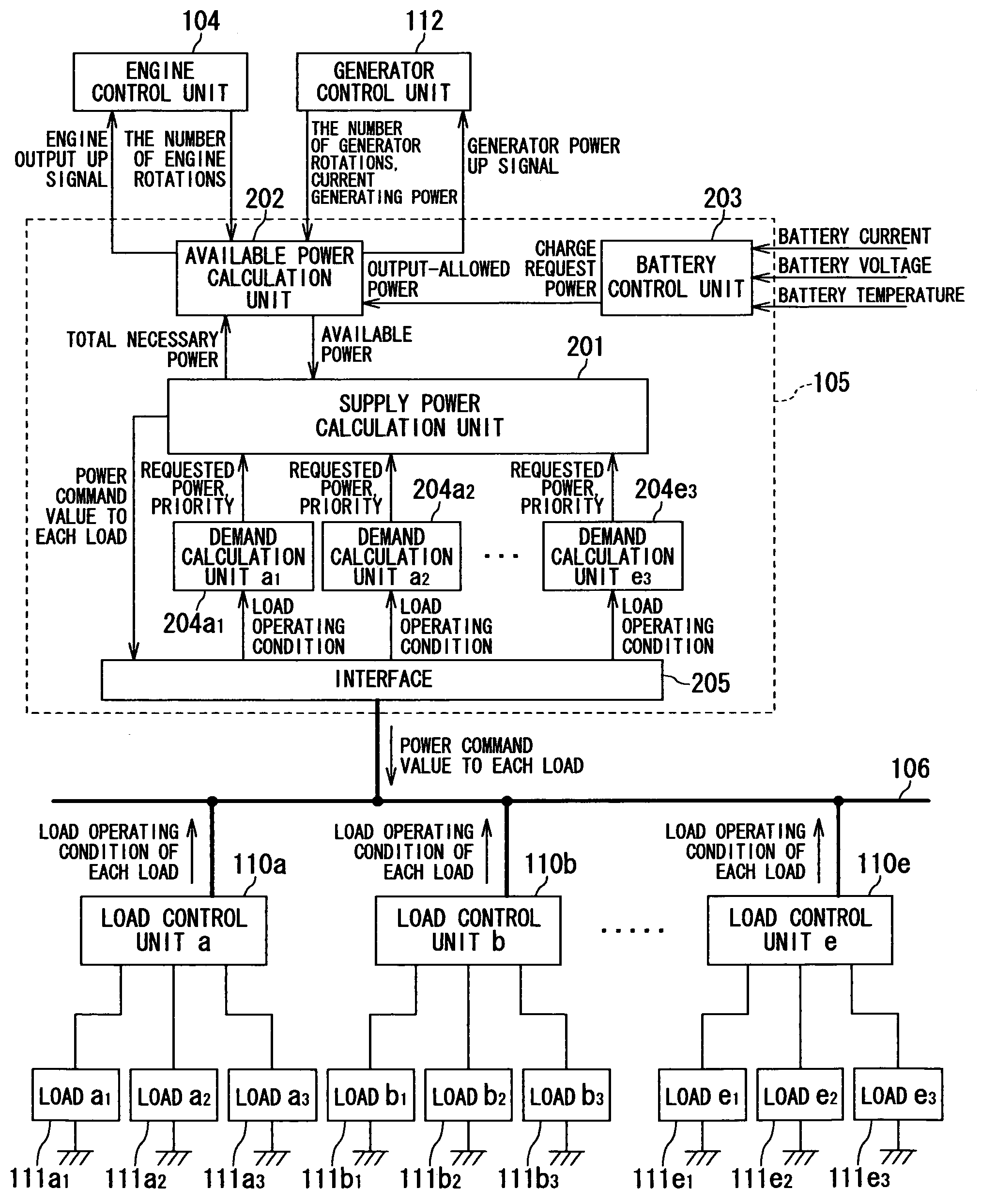
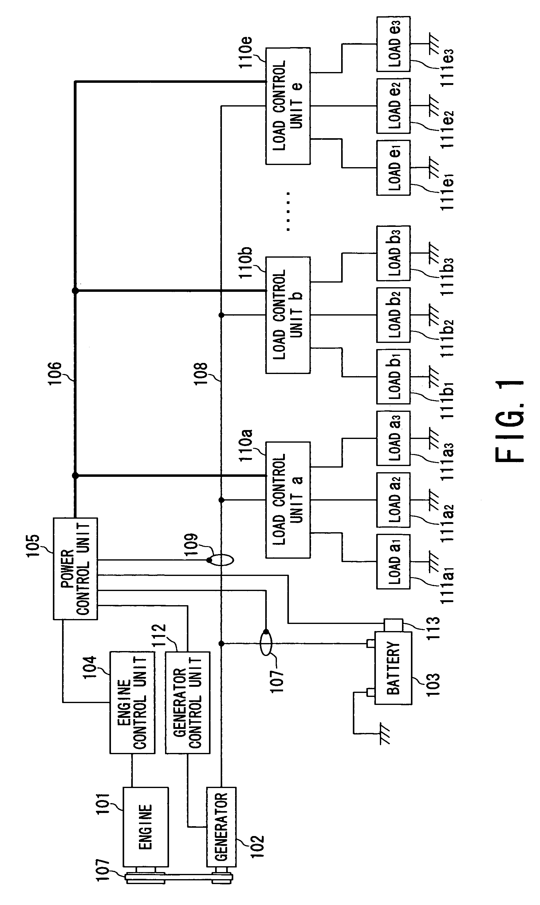
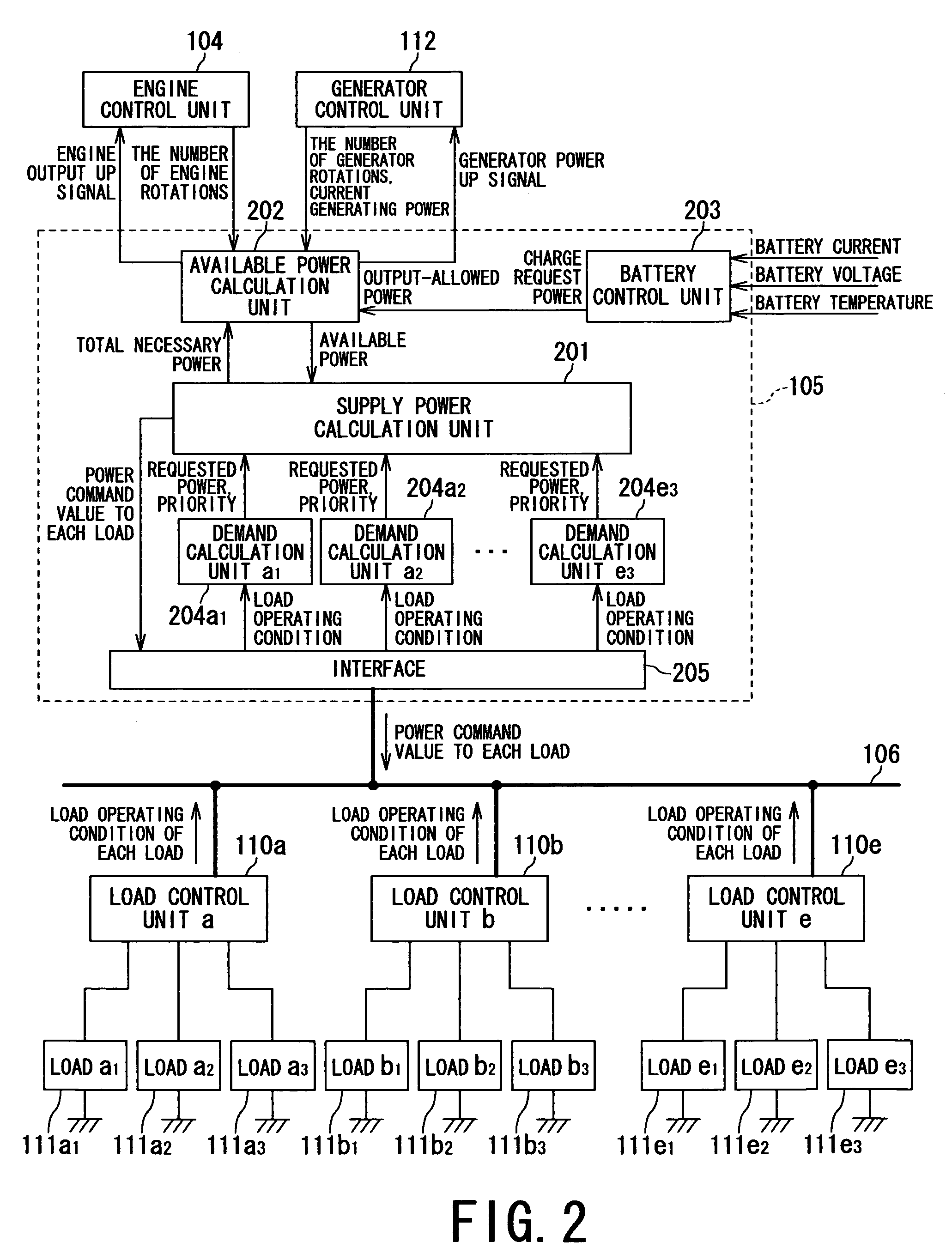
[0066]FIG. 1 is a block diagram showing a power supply system mounted on a vehicle, in which the power supply system is provided with the on-vehicle load driving and controlling system according to the first embodiment.

[0067]First of all, the configuration of the power supply system is provided with an engine 101, generator 102, battery 103, engine control unit 104, power control unit 105, load control units 110a to 110e, and generator control unit 112. The generator 102 is coupled with the engine 101 via a belt 107, and coupled with both of the battery 103 and the load control units 110a to 110e via a power supply line 108.

[0068]Each of the load control units 110a to 110e is in charge of controlling supply of power (electric power) to each group of loads 111a1 to 111a3 (to 111e1 to 111e3). Each of the load control units 110a ...

second embodiment

[0151](Second Embodiment)

[0152]Referring to FIG. 17, a second embodiment of the present invention will now be described. The present embodiment relates to another example of the routine for calculating the priority. FIG. 17 shows a subroutine for such calculation. FIG. 17 corresponds to FIG. 8 in the first embodiment, in which steps S1601 to S1604 are the same as the steps in FIG. 8.

[0153]The subroutine shown in FIG. 17 is different from that in FIG. 8 in that steps S1605, S1606 and S1607 are added. To be specific, after calculating the priority in the normal operation, it is determined at step S1605 whether or not a power command value to each load is less than an amount of necessary power of the load. If the determination is YES (the power command value is less than the necessary power amount), the processing is then executed at step S1606. At this step S1606, it is further determined whether or not the calculated priority at step S1602 is still less than a predetermined priority ...

third embodiment

[0155](Third Embodiment)

[0156]Referring to FIGS. 18 and 19, a third embodiment of the present invention will now be described. The present embodiment relates to another example of the routine for calculating the priority. FIG. 18 shows a subroutine for such calculation. FIG. 18 corresponds to FIG. 8 in the first embodiment, in which steps S1701 to S1704 are the same as the steps in FIG. 8.

[0157]The subroutine shown in FIG. 18 is different from that in FIG. 8 in that steps S1705 to S1709 are added. To be specific, after calculating the priority in the normal operation, it is determined at step S1705 whether or not a power command value (i.e., power to be supplied) to each load is less than an amount of necessary power of the load. If determined YES at step S1705 (i.e, the power command value is less than the necessary power amount), the processing goes to step S1706, at which the priority is within a predetermined range inherent to the load. If YES at step S1706 (i.e., the priority i...


PUM


Abstract

In an apparatus for driving and controlling plural on-vehicle electrical loads, an on-vehicle power supply generates power to be supplied the loads each having a priority. A power calculating device calculates a current available amount of the power to be supplied from the power supply, and a priority changing device changes one or more of the priorities on the basis of inputted information about a vehicle condition, the information including conditions of the loads. A command producing device produces a command value indicative of an amount of the power to be supplied to each of the loads by using the priorities. In this case, a sum of the power to be supplied to each load is kept within the available amount of the power to be supplied. A controller controls the power to be distributed to each of the loads on the basis of the command value.

Description

BACKGROUND OF THE INVENTION[0001]1. Technical Field[0002]The present invention relates to a method and apparatus for driving and controlling a plurality of electrical on-vehicle loads, and in particular to the method and apparatus that distributes electric power generated by an on-vehicle generator to the loads using pluralities given to the loads in advance.[0003]2. Related Art[0004]In recent years, the types of electrical loads (hereinafter, simply referred to as loads) mounted on vehicles, such as automobiles, and the total power consumption has been increased remarkably. It is supposed that this tendency will continue.[0005]In addition, there is a tendency of employing a load drive system configured only by an electrical system without using mechanical components, as provided by a steer-by-wire system, which connects an operation device and an actuator. Such load drive system is very significant in that the system is directly concerned with some fundamental functions of the vehi...

Claims


Application Information

Patent Timeline
IPC IPC(8): B60L1/00B60L3/00B60R16/02B60R16/03
CPCB60R16/0315
Inventor TANI, KEISUKEOBAYASHI, KAZUYOSHI
Owner DENSO CORP
Why Eureka
Try Eureka