Controlling electrical device based on temperature and voltage

a technology of electrical devices and control devices, applied in the direction of program control, testing/monitoring control systems, instruments, etc., can solve the problems of failure rate before the end of the lifetime, and failure rate that far exceeds the design lifetime, so as to improve the reliability characteristics of the device, reduce the operating performance, and permit strenuous use

Active Publication Date: 2018-09-04
APPLE INC
View PDF53 Cites 1 Cited by
  • Summary
  • Abstract
  • Description
  • Claims
  • Application Information

AI Technical Summary

Benefits of technology

[0004]In an embodiment, a lifetime controller is configured to monitor operating conditions for a device, and to control operating conditions based on the previously detected conditions to improve the reliability characteristics of the device while permitting strenuous use as available. For example, the lifetime controller may permit strenuous use when the device is first powered on. Once a specified amount of strenuous use has occurred, the controller may cause the operating performance to be reduced to limit the wear on the device, and thus help to extend the lifetime of the device. Similarly, if a device is used in less strenuous conditions, the controller may accumulate credit which may be expended by permitting the device to operate in more strenuous conditions for a period of time. By controlling the device in this fashion, a low lifetime failure rate for a set of devices may be maintained while permitting strenuous operation of the device (which could cause wear) for at least some periods of time to satisfy user demands.

Problems solved by technology

Beyond this service lifetime, the device may fail to operate correctly due to wear or other common aging effects.
While a given instance of a device may have a defect that causes the device to fail before the lifetime, generally the failure rate prior to the end of the lifetime is expected to be on the order of one in several million instances.
Such determinations are intentionally conservative, and thus numerous devices that do not frequently experience worst-case conditions may have lifetimes that far exceed the design lifetime.
While the additional lifetime can be welcome, it can also indicate at the device is over-engineered and possibly more expensive than necessary.
For example, the lifetime controller may permit strenuous use when the device is first powered on.
By controlling the device in this fashion, a low lifetime failure rate for a set of devices may be maintained while permitting strenuous operation of the device (which could cause wear) for at least some periods of time to satisfy user demands.

Method used


Image

  • Controlling electrical device based on temperature and voltage
  • Controlling electrical device based on temperature and voltage
  • Controlling electrical device based on temperature and voltage

Examples


Embodiment Construction

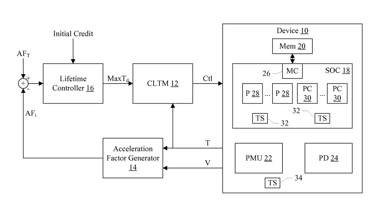
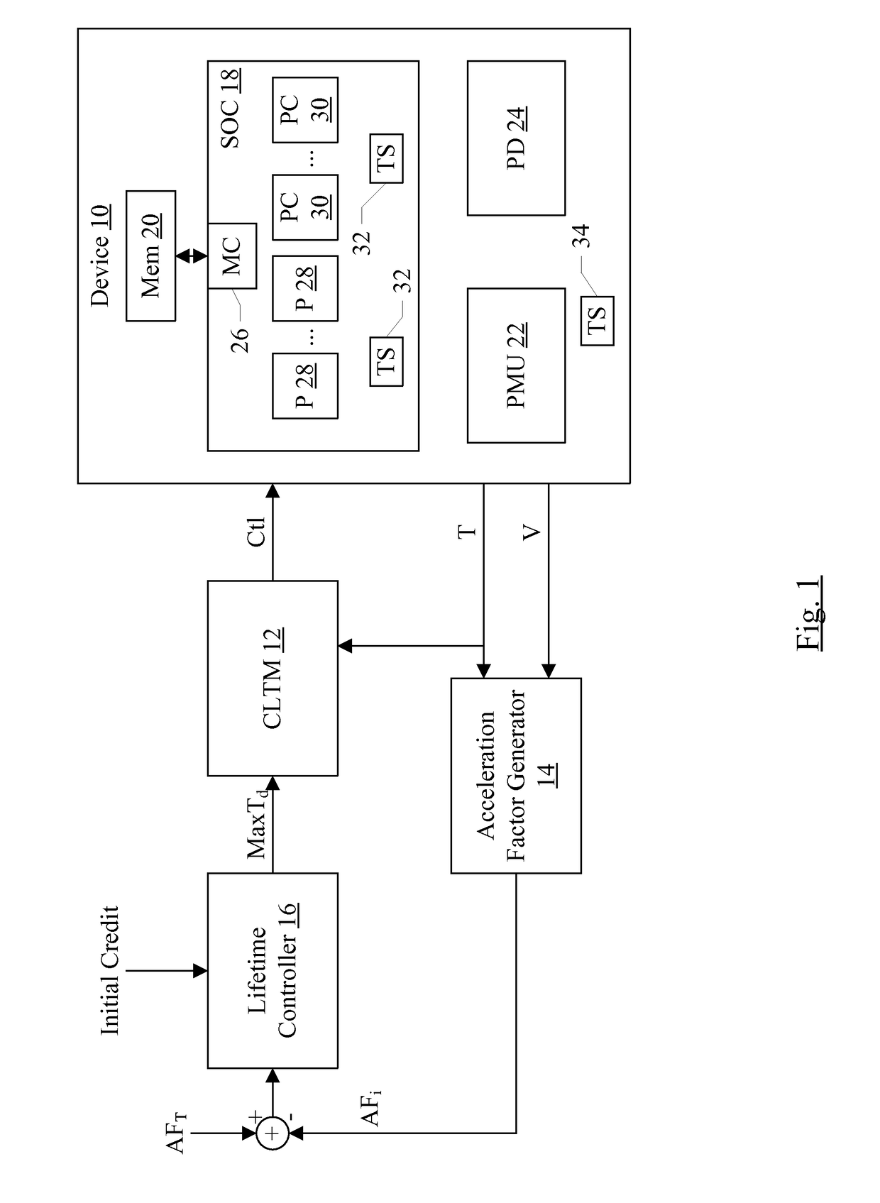
[0016]In various embodiments, a system may include an electrical device for which lifetime is to be managed. The electrical device may be any device. For example, the electrical device may include any of the following in some embodiments an integrated circuit, two or more integrated circuits, one or more integrated circuits mounted on a board with one or more other components, etc. The electrical device may be part of a product or the entire product, in various embodiments. The electrical device may have one or more operating parameters that are monitored to manage lifetime. Operating parameters may be any data that represents the operating conditions of the device. Exemplary parameters may include one or more supply voltage magnitudes, one or more supply current magnitudes, one or more operating temperatures, one or more operating clock frequencies, etc. Embodiments including a particular electrical device and operating parameters thereof are described in more detail as an example ...


PUM


Abstract

In an embodiment, a lifetime controller is configured to monitor operating conditions for a device, and to control operating conditions based on the previous conditions to improve the reliability characteristics of the device while permitting strenuous use as available. For example, the lifetime controller may permit strenuous use when the device is first powered on. Once a specified amount of strenuous use has occurred, the controller may cause the operating conditions to be reduced to reduce the wear on the device, and thus help to extend the lifetime of the device. Similarly, if a device is used in less strenuous conditions, the controller may accumulate credit which may be expended by permitting the device to operate in more strenuous conditions for a period of time.

Description

BACKGROUNDTechnical Field[0001]Embodiments described herein are related to lifetime management for an electronic device.Description of the Related Art[0002]Electronic devices are typically designed to a target service lifetime, during which the device is expected to operate correctly. Beyond this service lifetime, the device may fail to operate correctly due to wear or other common aging effects. While a given instance of a device may have a defect that causes the device to fail before the lifetime, generally the failure rate prior to the end of the lifetime is expected to be on the order of one in several million instances.[0003]Reliability analysis generally has to do with determining the worst case conditions that can cause the device to fail, and ensuring that the components of the device will not fail more often than the desired failure rate over the desired lifetime under those worst case conditions. Such determinations are intentionally conservative, and thus numerous devices...

Claims


Application Information

Patent Timeline
Patent Type & Authority Patents(United States)
IPC IPC(8): G06Q10/06G05B19/4065G06F17/18G05B13/02G05B23/02
CPCG05B13/02G05B2219/36347G05B2219/36291G05B23/0283G05B2219/50185G05B2219/37252G05B19/4065G05B2219/37245G05B2219/37256
Inventor HO, CHING E.OLIVA, ANTONIETTAISMAIL, JAMES S.DORSEY, JOHN G.COX, KEITHROHRER, NORMAN J.
Owner APPLE INC
Why Eureka
Try Eureka