
Battery system, battery monitoring method and apparatus

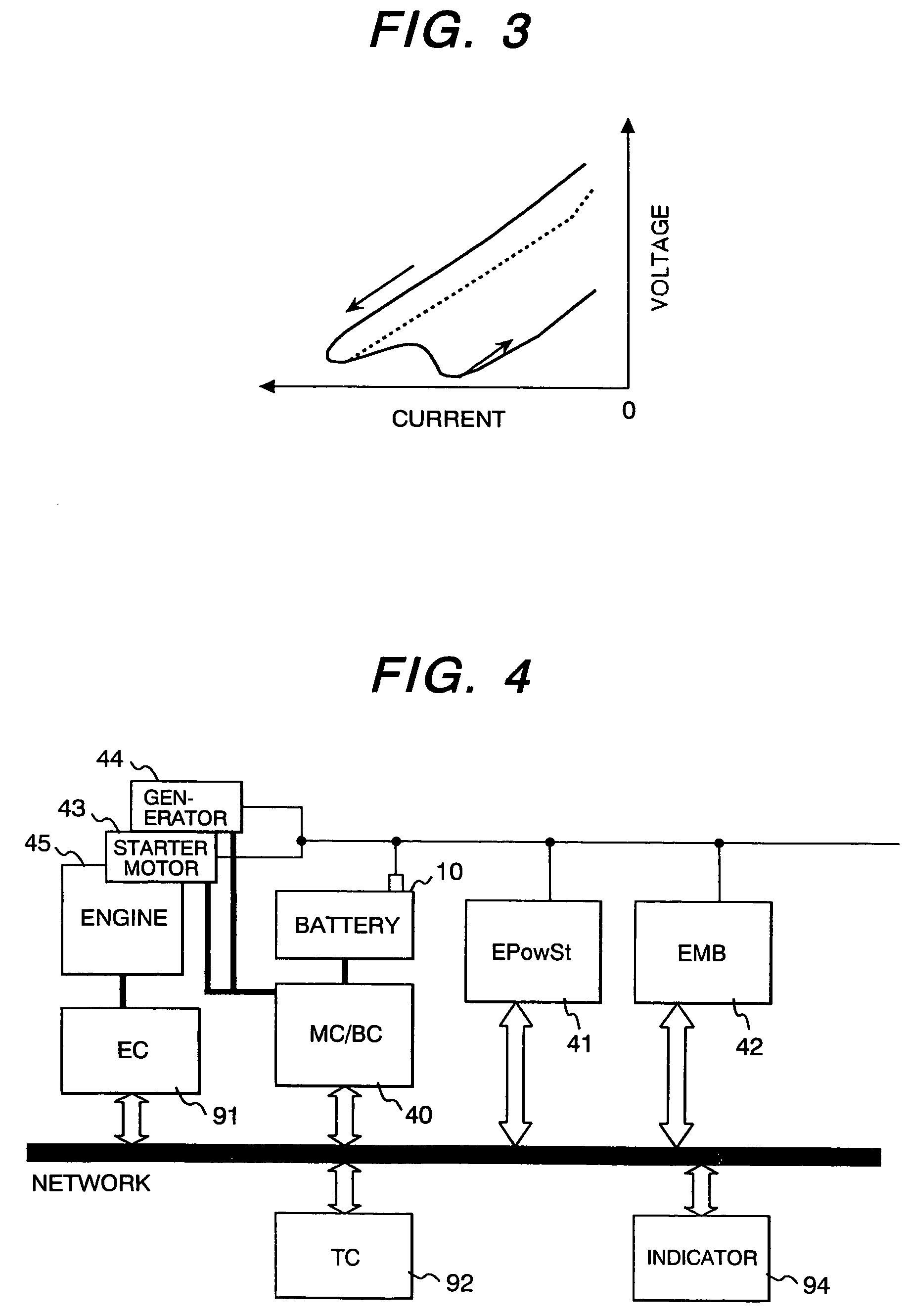
a battery system and battery monitoring technology, applied in secondary cell servicing/maintenance, dynamo-electric converter control, instruments, etc., can solve problems such as battery not being able to start the engine, battery not being able to restart the engine, and publication cannot be used for the battery of the car

Inactive Publication Date: 2007-02-06
HITACHI LTD +1
View PDF5 Cites 43 Cited by
  • Summary
  • Abstract
  • Description
  • Claims
  • Application Information

AI Technical Summary

Benefits of technology

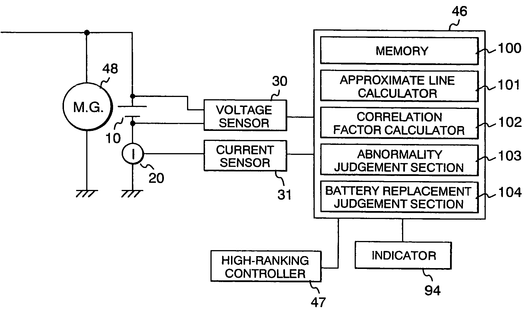
The present invention provides a method, equipment, and battery system for monitoring the abnormality of battery equipment which is charged to store power and discharges the stored power to a load. The invention measures the voltage and current during power discharge to the load, and analyzes the voltage recovery characteristics to diagnose any abnormality in the battery equipment. This can help to prevent malfunctions or failures in the battery system, improving its overall reliability and performance.

Problems solved by technology

If the battery does not have a sufficient power supply after the engine is stopped, it will not be able to restart the engine.
If any of the cells malfunctions and falls into the state of inverse charge, a voltage drop equal or greater by 2 volts or more than the normal state arises at the time of discharging and the battery may not be able to start the engine.
Due to a charging current after the large load application, the battery voltage soon exceeds the no-load voltage, and therefore the scheme of this patent publication cannot be used for the car battery.
For this reason, it is difficult to estimate a deficiency of the power supply during a run and the failure of engine restarting etc.

Method used


Image

  • Battery system, battery monitoring method and apparatus
  • Battery system, battery monitoring method and apparatus
  • Battery system, battery monitoring method and apparatus

Examples


Embodiment Construction

[0028]Embodiments of this invention will be explained in detail with reference to the drawings.

[0029]This invention has two points. The first point is determining a battery characteristics to be utilized for abnormality anticipation, and the second point is determining an algorithm of the judgment of abnormality.

[0030]A usual lead battery for starting a car engine (12-volt lead battery) consists of six lead battery cells connected in series. If these battery cells have different charge states and any battery cell falls into the state of over discharge or inverse charge during the discharge operation due to the disparity of self-discharge rate, charging efficiency, and the rise of self-discharge rate as a result of performance deterioration, there will arise such problems as inadequate discharge output and sudden deterioration of performance. On this account, it is necessary to monitor and control the battery so that all battery cells are equal in charge state and do not fall into th...


PUM

PropertyMeasurementUnit
voltageaaaaaaaaaa
voltageaaaaaaaaaa
voltageaaaaaaaaaa

Abstract

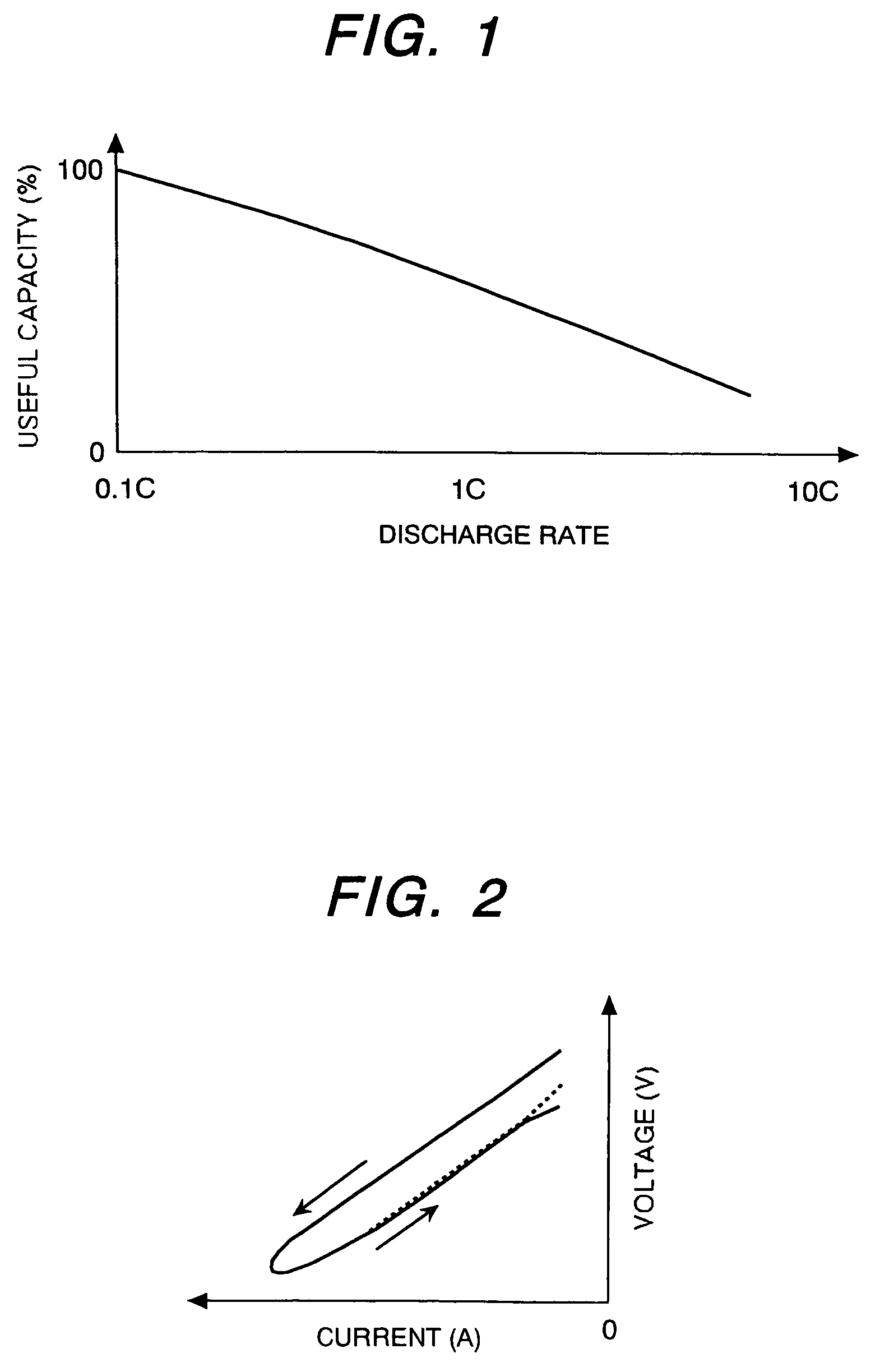
A battery performance monitoring system anticipates the sudden fall of battery output. The system measures the battery voltage at a time point when the discharge current of a battery becomes smaller than the reference current value or at a time point when the current to the load which is connected to the battery becomes smaller than the reference current value, and judges the battery to be abnormal if the difference of the measured battery voltage from the approximate formula in regard to the current-voltage relation in the former half of a same discharge event becomes out of the reference range.

Description

FIELD OF THE INVENTION[0001]The present invention relates to a method of performance assessment of a secondary battery (will be called simply “battery” hereinafter) and battery equipment, and particularly to a system for monitoring whether a battery installed in a motor car or the like is functioning normally.BACKGROUND OF THE INVENTION[0002]Vehicles such as motor cars are each equipped with a lead battery as a secondary battery, and it is used as energy source of engine starting, lighting, fuel injection, etc. It is desired to anticipate the fall of output of the lead battery. If the battery does not have a sufficient power supply after the engine is stopped, it will not be able to restart the engine.[0003]A usual 12-volt lead battery consists of six 2-volt cells connected in series. If any of the cells malfunctions and falls into the state of inverse charge, a voltage drop equal or greater by 2 volts or more than the normal state arises at the time of discharging and the battery m...

Claims


Application Information

Patent Timeline
Patent Type & Authority Patents(United States)
IPC IPC(8): H02J7/00G01N27/416G01R31/36B60L11/18H01M8/00H01M10/42H01M10/48H02J7/14H02P11/00
CPCB60L11/1851G01R31/3624H02J7/1461Y02T10/705Y02T10/7005G01R31/3842B60L58/10Y02T10/70H02J7/00306H02J7/0048H02J7/14
Inventor KINOSHITA, TAKUYAMIYAZAKI, HIDEKIEMORI, AKIHIKOOKOSHI, TETSUROHIRASAWA, TOKIYOSHI
Owner HITACHI LTD
Learn More