Dynamic logic return-to-zero latching mechanism

a latching mechanism and dynamic logic technology, applied in the field of latching circuits, can solve the problems of pipelined architecture complexity, time required to perform a given logical evaluation, and etc., and achieve the effect of reducing the complexity of pipelined architectures

Active Publication Date: 2007-02-06
IP FIRST
View PDF22 Cites 10 Cited by
  • Summary
  • Abstract
  • Description
  • Claims
  • Application Information

AI Technical Summary

Benefits of technology

[0011]The dynamic circuit may be implemented as multiple dynamic circuits, each receiving a corresponding input signal and each pre-charging a corresponding pre-charged node. The latching circuit may be implemented as multiple latching circuits, each coupled to a corresponding dynamic circuit, each receiving a corresponding input signal, and each having an output that is wire-ORed coupled to the output node. The use of multiple dynamic and corresponding latching circuits enables implementation of many different logic functions that may vary from very simple to very complex. In one exemplary embodiment, an exclusive-OR logic function is implemented.

Problems solved by technology

The complexity of pipelined architectures has grown along with the complexity of logical evaluations required within the individual stages of such architectures.
Such techniques, however, only compensate in multiple / subsequent stages for the amount of time that is required to perform a given logical evaluation.
The real problem is that present day logic evaluation circuits (e.g., multiplexers, encoders, decoders, bit comparators, etc.) take too long to generate their outputs.

Method used


Image

  • Dynamic logic return-to-zero latching mechanism
  • Dynamic logic return-to-zero latching mechanism
  • Dynamic logic return-to-zero latching mechanism

Examples


Embodiment Construction

[0024]The following description is presented to enable one of ordinary skill in the art to make and use the present invention as provided within the context of a particular application and its requirements. Various modifications to the preferred embodiment will, however, be apparent to one skilled in the art, and the general principles defined herein may be applied to other embodiments. Therefore, the present invention is not intended to be limited to the particular embodiments shown and described herein, but is to be accorded the widest scope consistent with the principles and novel features herein disclosed.

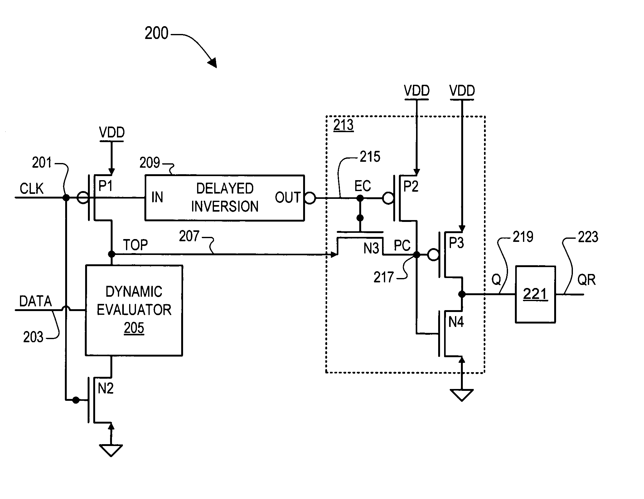
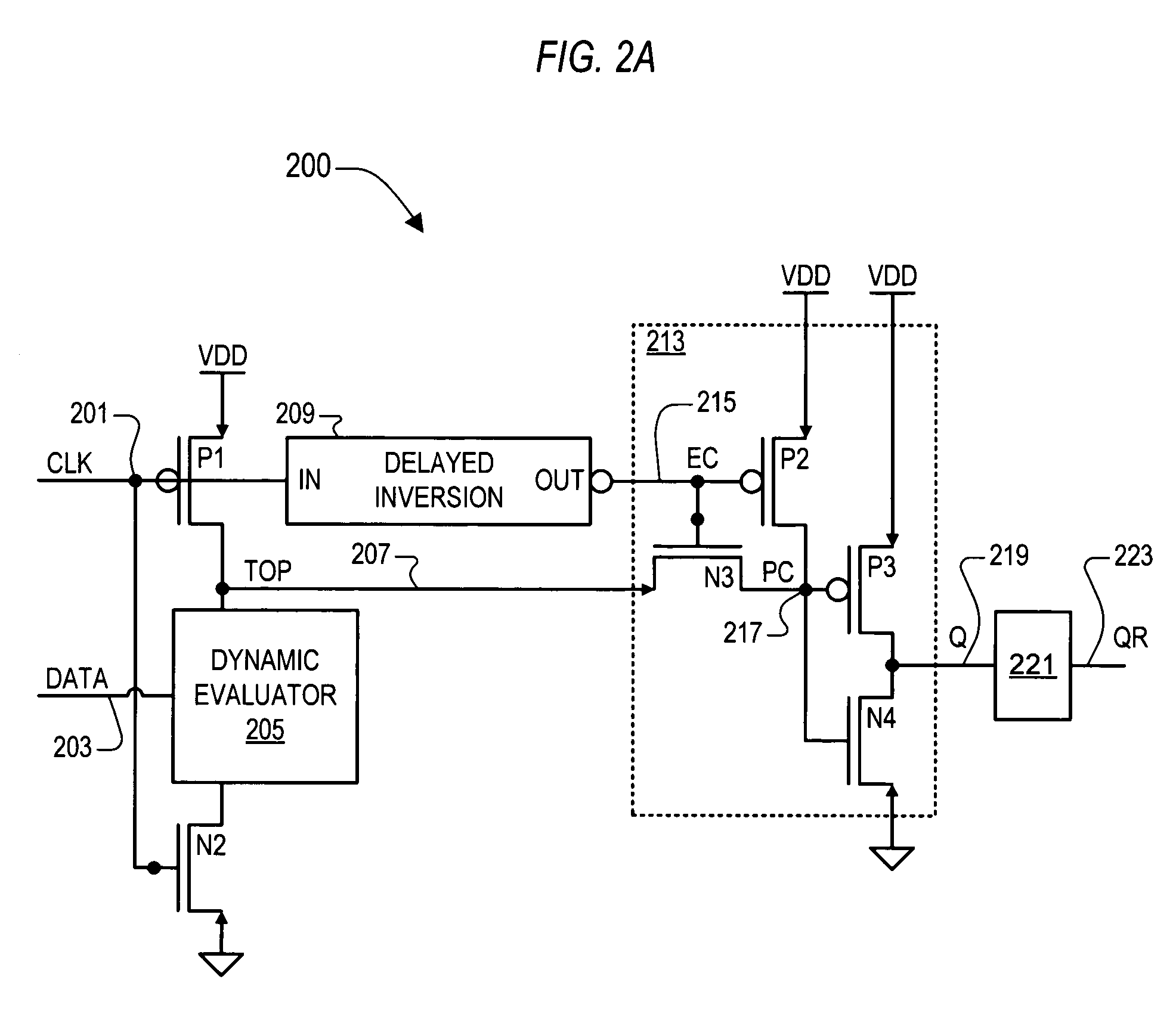
[0025]The inventor of the present application has recognized the need for providing latched outputs for logic circuits in which speed is a critical factor. He has therefore developed an integral return-to-zero (RTZ) latching mechanism for use within complex logic evaluation circuits that employ dynamic circuit principles to enhance the speed by which an evaluant is determined, ...


PUM


Abstract

A dynamic logic return-to-zero (RTZ) latching mechanism including a complementary pair of evaluation devices responsive to a clock signal, a dynamic evaluator, delayed inversion logic, and latching logic. The dynamic evaluator is coupled between the complementary pair of evaluation devices at a pre-charged node and evaluates a logic function based on at least one input data signal. The latching logic asserts the logic state of an output node based on the state of the pre-charged node during an evaluation period between an operative edge of the clock signal and the next edge of an evaluation complete signal, which is a delayed and inverted version of the clock signal. The output node is returned to zero between evaluation periods. A footless latching domino circuit may be added to convert the RTZ output to a registered output signal.

Description

CROSS-REFERENCE TO RELATED APPLICATIONS[0001]This application claims the benefit of U.S. Provisional Application No. 60 / 432,693, filed on Dec. 10, 2002, which is herein incorporated by reference for all intents and purposes.[0002]This application is related to U.S. patent application Ser. No. 10 / 730,703, filed on Dec. 9, 2003, now U.S. Pat. No. 6,965,254. The aforementioned application is commonly owned and has at least, one common inventor, and is herein incorporated by reference in its entirety for all intents and purposes:BACKGROUND OF THE INVENTION[0003]1. Field of the Invention[0004]The present invention relates to latch circuits, and more particularly to a dynamic logic return-to-zero (RTZ) latching mechanism for logic evaluation functions, where the latching mechanism exhibits a significantly reduced data-to-output time.[0005]2. Description of the Related Art[0006]The complexity of pipelined architectures has grown along with the complexity of logical evaluations required wit...

Claims


Application Information

Patent Timeline
Patent Type & Authority Patents(United States)
IPC IPC(8): H03K19/096H03K3/286G06F15/00
CPCH03K19/0963
Inventor LUNDBERG, JAMES R.
Owner IP FIRST
Why Eureka
Try Eureka