
Operating system for a motorized barrier operator

a technology of motorized barriers and operating systems, which is applied in the direction of computer control, program control, dynamo-electric motors/converters stoppers, etc., can solve the problems of affecting the normal operation of the system, so as to achieve easy identification

Active Publication Date: 2007-02-06
GMI HLDG
View PDF27 Cites 33 Cited by
  • Summary
  • Abstract
  • Description
  • Claims
  • Application Information

AI Technical Summary

Benefits of technology

[0014]Yet another object of the present invention is to provide additional functions which may include an auto-close feature wherein the auto-close feature is provided with an operator-set or a user-adjustable time period for allowing a door or barrier to remain open for a period of time prior to beginning of closure of the barrier. Still another function may provide for blocking of all other wireless or remote transmitters such that a wall station transmitter is the only transmitter recognized by the operator system. Still yet another object of the present invention is to provide a function that permits the auto-close feature to only be enabled if a keyless transmitter is taught to the operator system. Still yet another object of the present invention is to provide an auto-close feature that is enabled only if a signal is previously received from a remote transmitter or a keyless transmitter.
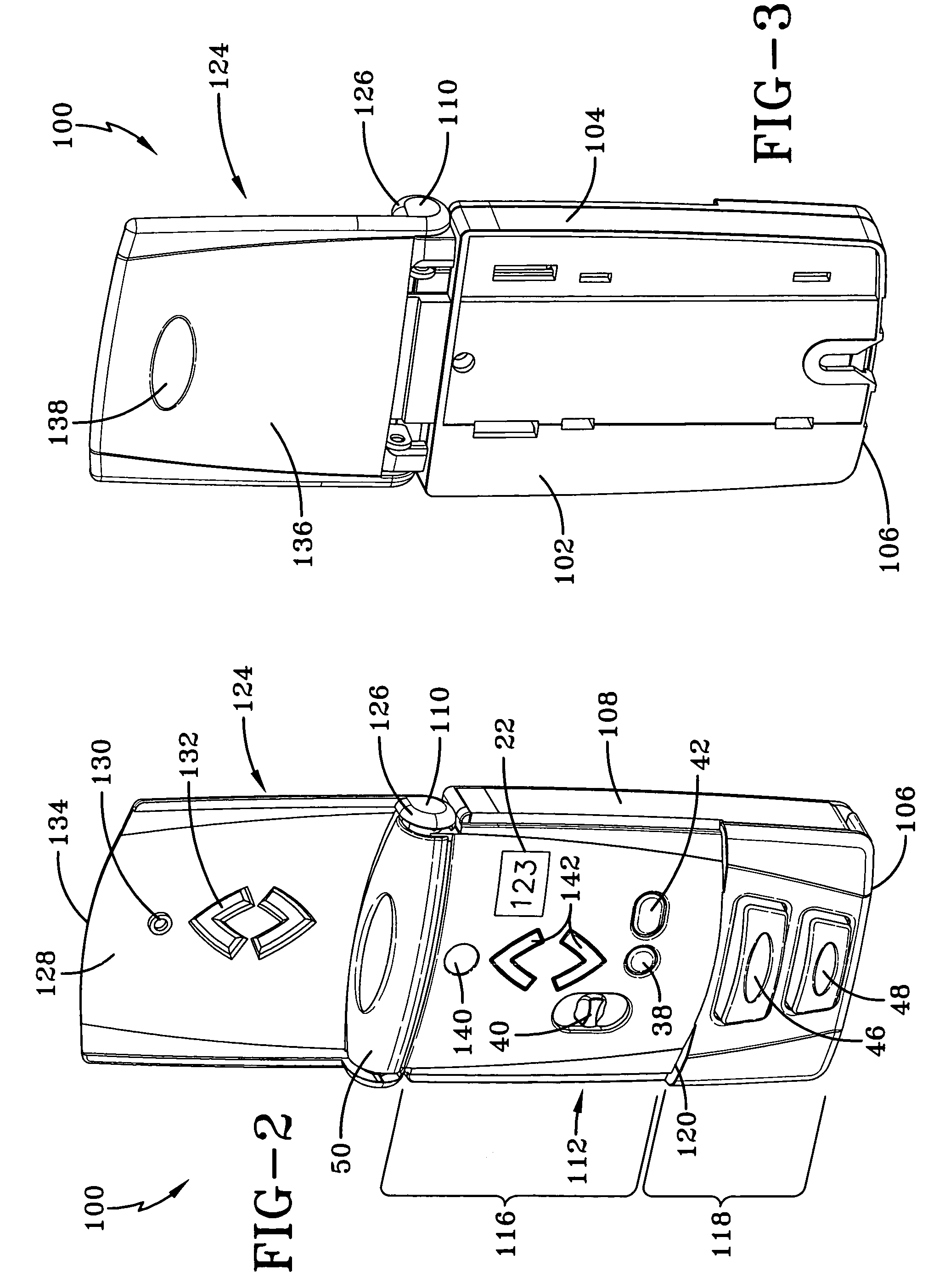
[0015]Still further objects of the present invention allow for a wall station to provide a plurality of buttons wherein a certain plurality of buttons are concealed from immediate use. Yet another object of the present invention is to provide a wall station transmitter wherein selected buttons of the transmitter are illuminated for easy identification in a dimly lit environment. Still yet another object of the present invention is to provide for a wall station which provides a cover that is used to conceal the certain plurality of buttons and wherein the cover is movable in the concealing position to allow for actuation of at least one of or a selected number of the concealed buttons. Still yet another object of the present invention is to provide for a wall station wherein the cover that is utilized to conceal at least some of the buttons is selectively illuminated. Another object of the present invention is to provide a detachable cover to enclose batteries within a battery compartment of the wall station housing.

Problems solved by technology

But due to their weight and the inconvenience of opening and closing the door, motors are now connected to the door.
The add-on devices are susceptible to failure or damage and as such may interfere with the normal operation of system.
And if the add-on device is in proximity to other devices the possibility of inadvertent button actuation is substantially increased.
Indeed, current systems are simply not user friendly in that they can not be seen in the dark nor do they provide sufficient tactile distinctions to enhance their use.
Nor do current systems provide an integrated auto-close feature in conjunction with other functions provided on a multi-function wall station.
And these systems do not provide both the ability to easily disconnect and / or adjust the timing of the auto-close feature.
Finally, the systems do not provide an auto-close feature that can only be enabled if a keyless entry transmitter or other remote transmitter is also taught to the operating system.
In summary, current movable barrier operator systems do not provide a complete and integrated functional wall station that is ergonomically designed and efficient in use and operation.

Method used


Image

  • Operating system for a motorized barrier operator
  • Operating system for a motorized barrier operator
  • Operating system for a motorized barrier operator

Examples


Embodiment Construction

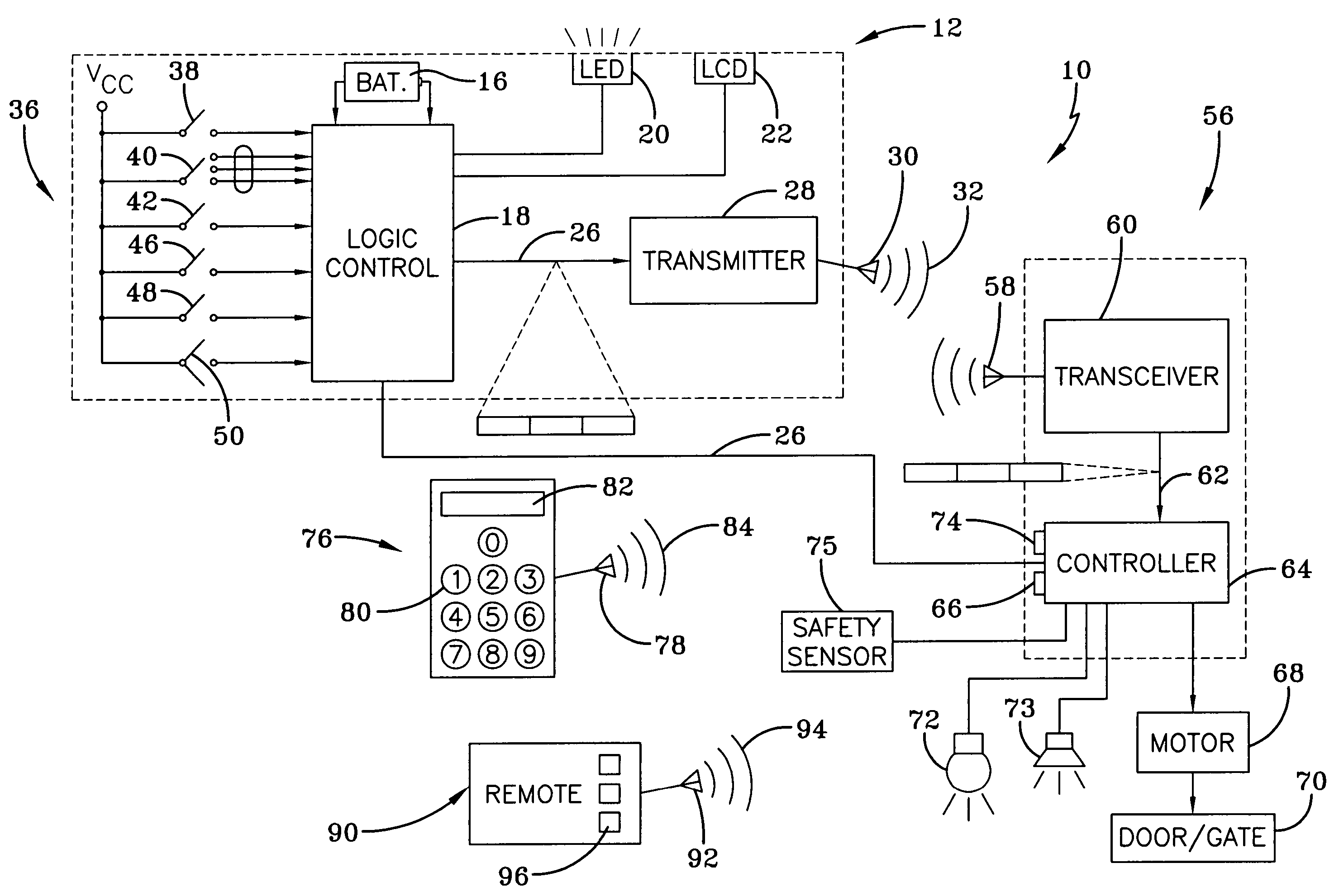
[0032]An operating system for a motorized door or gate operator according to the concepts of the present invention, depicted in FIG. 1 of the drawings, is generally indicated by the numeral 10. The system 10 may be employed in conjunction with a wide variety of movable barrier doors or gates, wherein the doors are of the type utilized in garages, commercial and utility buildings, and other structures, as well as windows or other closure members, all of which may be linear, curved, or otherwise non-linear, in whole or in part. Such barriers or other members are commonly constructed of a variety of materials such as wood, metal, various plastics, or combinations thereof. The lower extremity of doors or other member of these various types may be substantially rectangular or may be profiled in any number of ways for the positioning of reinforcing members or other purposes. In the preferred use, the present invention is utilized with residential-type garage doors. Generally, the system 1...


PUM


Abstract

An operating system which utilizes a multi-functional wall station for a motorized barrier includes an operator for controlling movement of a barrier between various positions. The operator may receive signals from a wireless or wired wall station transmitter, a wireless keyless entry device and / or a portable remote transmitter device. The multi-function wall station provides for selective concealment of certain switches or buttons which are not commonly used in the day-to-day operation of a wall station. For example, the up / down switch may be actuated by a hinged cover which conceals other selected operational buttons and wherein those operational buttons are only accessed upon opening of the hinged cover. The wall station also provides a periodic lighting element so as to easily direct the user to push the hinge cover to initiate up / down movement of the barrier. The multi-function wall station also provides for an operational selection wherein the door may be closed in a normal manner; by an auto-close feature, wherein the door closes after a predetermined period of time; or a RF block mode, wherein the station prevents transmission of any remote radio frequency signals to the operating system. The auto-close feature may only be enabled upon actuation of a keyless entry device so as to allow the user to re-enter the garage in the unfortunate circumstance of being locked out of the garage.

Description

TECHNICAL FIELD[0001]Generally, the present invention relates to a garage door operator system for use on a closure member moveable relative to a fixed member. More particularly, the present invention relates to a wall station transmitter for controlling the operation of a movable barrier, such as a gate or door, between a closed position and an open position. More specifically, the present invention relates to a wired or wireless wall station control for a door or gate operator, wherein the wall station has a plurality of buttons or touch pad keys which may be selectively concealed, and wherein actuation of a button implements a corresponding function of the operating system. One function in particular provides an auto-close function which automatically closes the movable barrier after a pre-determined period of time.BACKGROUND ART[0002]As is well known, garage doors or gates enclose an area to allow selective ingress and egress to and from the area. Garage doors initially were mov...

Claims


Application Information

Patent Timeline
Patent Type & Authority Patents(United States)
IPC IPC(8): G05B19/00H02P1/00E05F15/16E05F15/20H01H9/18
CPCG07C9/00182E05F15/79E05F15/668E05Y2201/41E05Y2400/66E05Y2400/80E05Y2900/106G07C2009/00793E05F15/00E05Y2800/424E05Y2800/00E05Y2600/452E05F15/77G07C2009/00928
Inventor MULLET, WILLIS J.DAVIES, DAVID B.BACKSTROM, MIKAELWILMOT, ERICALSBERG, KEITHMURRAY, JAMES S.
Owner GMI HLDG
Learn More