Method for determination of composition of the gas mixture in a combustion chamber of an internal combustion engine with exhaust gas recirculation and correspondingly configured control system for an internal combustion engine

a technology of combustion chamber and gas mixture, which is applied in the direction of electrical control, process and machine control, instruments, etc., can solve the problems of inability to calculate the type of sensor signal used in the calculation of the exhaust mass situated in the combustion chamber, and the inability to determine the fresh air mass beset by errors

Inactive Publication Date: 2007-02-13
VOLKSWAGEN AG
View PDF36 Cites 48 Cited by
  • Summary
  • Abstract
  • Description
  • Claims
  • Application Information

AI Technical Summary

Benefits of technology

[0030]Overall, the mass and composition of the gas mixture admitted by the combustion chamber of the internal combustion engine, for example, a diesel engine, can be exactly determined by means of the present invention, so that an emission-optimal regulation of the internal combustion engine is possible, based on precise knowledge of the mass and composition of the fresh air mass and exhaust mass in the combustion chamber of the internal combustion engine. A number of quantities of state from information known anyway can then be obtained without using separate or additional sensors, so that new control and regulation strategies are made possible.
[0038]Overall, state quantities of the exhaust line of an internal combustion engine, for example, a diesel engine, can therefore be determined exactly and by simple means by evaluating already known state quantities. The use of additional sensors is not required for this. New control and diagnosis methods within the corresponding engine management system are possible by the possible determination of state quantities of the exhaust line, which permits, for example, emission-optimal regulation of the internal combustion engine.
[0075]To implement a method for control of an internal combustion engine with exhaust gas recirculation, as well as a correspondingly configured control system for an internal combustion engine, with which control of the internal combustion engine is possible as a function of state quantities, determined as effectively as possible without requiring additional sensors of this connection between the mixing site and the intake valves of the internal combustion engine, a physically based model can be applied to determine different state quantities, referred to the connection or connection section between the mixing site, at which the return exhaust is mixed with the admitted fresh air, and the intake valves of the internal combustion engine, which simulates the behavior of this connection, in order to be able to control or regulate in emission-optimal fashion automatically the different operating parameters of the internal combustion engine, using this model. By means of the model, the fresh air or exhaust mass in this connection, or also the gas temperature in this connection, can be determined from already known state quantities without using additional sensors, so that specific operating parameters of the internal combustion engine dependent on it, like the fuel injection amount or the fuel injection time, etc., can be controlled or regulated in emission-optimal fashion.
[0108]Overall, the fresh air mass flow of an internal combustion engine, for example, a diesel engine, can therefore be determined exactly with simple means by evaluating already known state quantities. The use of additional sensors, especially a hot film-air mass sensor ordinarily required to determine the fresh air mass flow in the intake line, is not necessary for this. By simple possible determination of the exhaust gas recirculation mass flow, new control and diagnosis methods within the corresponding engine management system are therefore possible, which permits, for example, emission-optimal regulation of the internal combustion engine.
[0134]Overall, the exhaust gas recirculation mass flow of an internal combustion engine, for example, a diesel engine, can be therefore determined exactly with simple means by evaluation of already known state quantities. The use of additional sensors is not necessary for this. By the therefore simple possible determination of an exhaust gas recirculation mass flow, new control and diagnosis methods within the corresponding engine management system are possible, which permits, for example, an emission-optimal regulation of the internal combustion engine.

Problems solved by technology

Because of the fresh air storage behavior of the intake line, this determination of the fresh air mass is beset with errors in the dynamic engine operating phases.
Moreover, this type of sensor signal cannot used to calculate the exhaust mass situated in the combustion chamber, which is returned via exhaust gas recirculation of the internal combustion engine and mixed with the admitted fresh air at an exhaust gas recirculation mixing site.

Method used


Image

  • Method for determination of composition of the gas mixture in a combustion chamber of an internal combustion engine with exhaust gas recirculation and correspondingly configured control system for an internal combustion engine
  • Method for determination of composition of the gas mixture in a combustion chamber of an internal combustion engine with exhaust gas recirculation and correspondingly configured control system for an internal combustion engine
  • Method for determination of composition of the gas mixture in a combustion chamber of an internal combustion engine with exhaust gas recirculation and correspondingly configured control system for an internal combustion engine

Examples


Embodiment Construction

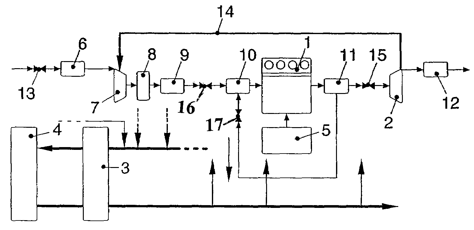
[0158]An internal combustion engine 1 with four combustion chambers or cylinders is shown in FIG. 1. The internal combustion engine 1 is coupled to an exhaust gas turbo-supercharger (ATL), which includes a turbine 2 and a compressor 7, in which the turbine and the compressor 7 are mounted on a common shaft, the so-called turbo-supercharger shaft 14. The turbine 2 uses the energy contained in the exhaust of the internal combustion engine 1 to drive the compressor 7, which takes in fresh air via an air filter 6 and forces pre-compressed air into the individual combustion chambers of internal combustion engine 1. The exhaust gas turbo-supercharger formed by turbine 2, compressor 7 and turbo-supercharger shaft 14 is only coupled to the internal combustion engine 1, in terms of flow, through the air and exhaust mass flow.

[0159]The air, admitted and pre-compressed by the compressor 7 via air filter 6, is fed via a charge air cooler (LLK) 8, which reduces the exhaust temperature and theref...


PUM


Abstract

An engine management system uses physically based models to determine the composition and mass of the fresh air / exhaust gas mixture suctioned by an internal combustion engine. The models are closely coupled to each other in a partial manner and are used to simulate the filling of the combustion chamber with the suctioned fresh air / waste gas mixture in order to simulate the flow of the mass of re-circulating exhaust gas, the behavior of the exhaust gas manifold upstream and downstream from a turbine, the storage behavior of the intake manifold, and the behavior of the intake pipe or inlet manifold whereby the fresh air / exhaust gas mixture is fed to the combustion engine from a corresponding mixing point where the suctioned fresh air is mixed with the exhaust gas re-circulated via the exhaust gas re-circulation line. As a result, a plurality of additional state variables can be determined without additional sensors.

Description

CROSS REFERENCE TO RELATED APPLICATION[0001]This application is a continuation of copending International Application No. PCT / EP02 / 12580 filed Nov. 11, 2002 which designates the United States, and claims priority to German application no. 101 58 262.5 filed Nov. 28, 2001, German application no. 101 58 247.1 filed Nov. 28, 2001, German application no. 101 58 261.7 filed Nov. 28, 2001, German Application No. 101 58 250.1 filed Nov. 28, 2001, and German Application No. 101 58 249.8 filed on Nov. 28, 2001.TECHNICAL FIELD OF THE INVENTION[0002]The present invention concerns a method for determination of the composition of the gas mixture in a combustion chamber of an internal combustion engine with exhaust gas recirculation, as well as a correspondingly configured control system in the internal combustion engine, for example, a diesel engine.DESCRIPTION OF THE RELATED ART[0003]Precise knowledge of the mass and composition of the admitted gas mixture, i.e., the fresh air / exhaust mixture, ...

Claims


Application Information

Patent Timeline
Patent Type & Authority Patents(United States)
IPC IPC(8): F02B33/44F02M25/07G01M19/00F02B47/08F02D41/00F02D41/18G01M99/00
CPCF02D41/0007F02D41/145F02D41/18F02M25/0754F02M25/0755F02D41/0072Y02T10/47F02D2041/1433F02D2200/0402F02D2200/0406F02D2200/0408F02D2200/703F02M25/0707F02M25/0713Y02T10/144F02M26/46F02M26/05F02M26/10F02M26/47Y02T10/12Y02T10/40
Inventor NITZKE, HANS-GEORGREBOHL, THORSTENJESCHKE, JENS
Owner VOLKSWAGEN AG
Why Eureka
Try Eureka