Air chiller unit

a chiller unit and air technology, applied in the field of air chiller units, can solve the problems of further dew condensation, achieve the effects of reducing the number of times for dehumidifying the device, preventing noise leakage, and reducing the dew condensation

Inactive Publication Date: 2007-02-13
JAMCO
View PDF13 Cites 5 Cited by
  • Summary
  • Abstract
  • Description
  • Claims
  • Application Information

AI Technical Summary

Benefits of technology

[0014]Thus, dew condensation can be reduced, and the number of times for dehumidifying the device can be reduced.
[0015]Moreover, during operation of the air chiller unit, the drain valve is closed due to negative pressure, preventing noise from leaking.

Problems solved by technology

The noise generated inside the air chiller unit is leaked through the drain to the passenger cabin, and highly moist outside air enters the air chiller unit through the drain, causing further dew condensation.

Method used


Image

  • Air chiller unit
  • Air chiller unit
  • Air chiller unit

Examples


Embodiment Construction

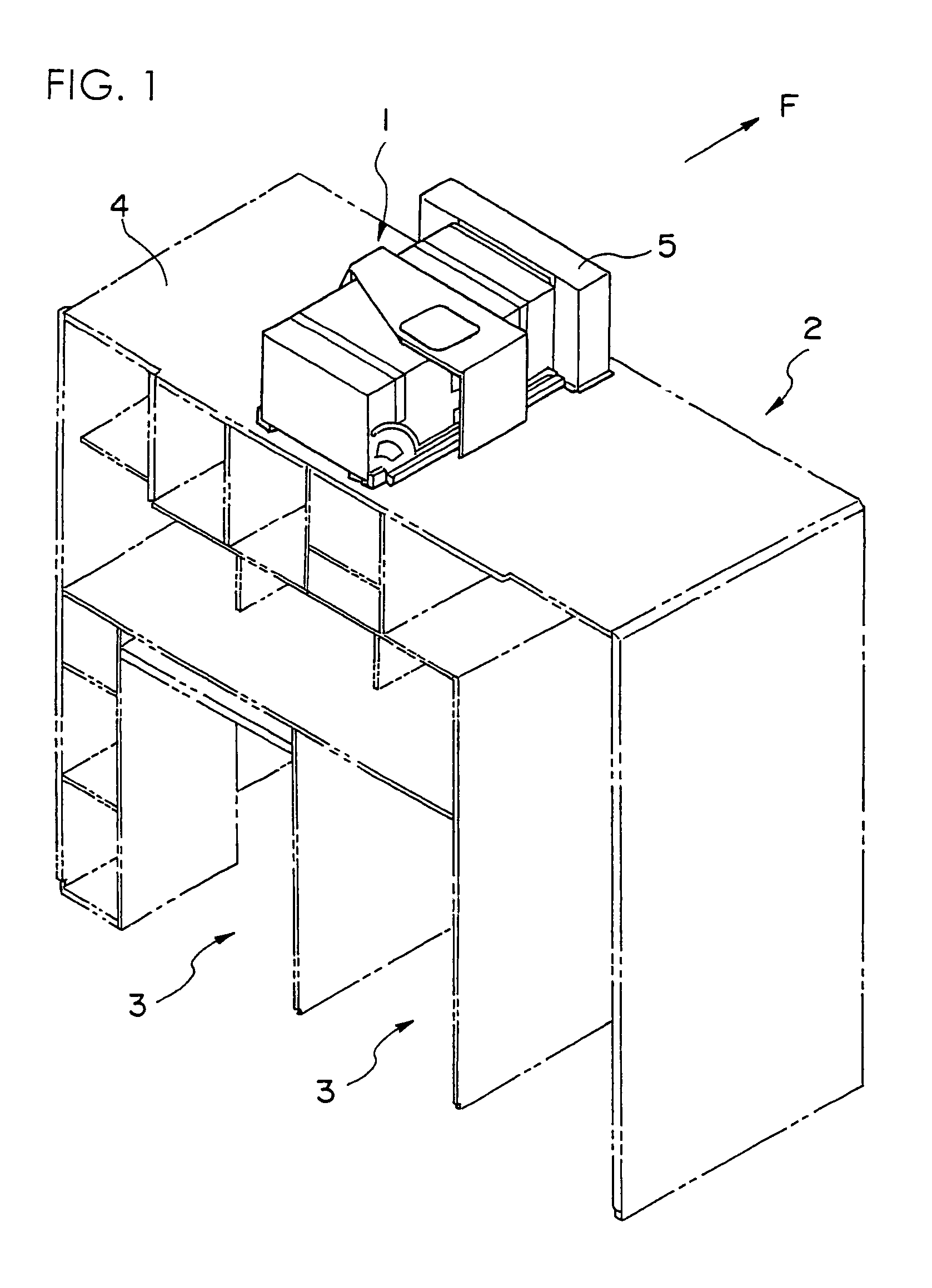
[0027]FIG. 1 is an explanatory view showing the general structure of a galley equipped with an air chiller unit according to the present invention.

[0028]The galley denoted as a whole by reference number 2 is formed of panel members, and equipped with multiple shelves and storages for storing cooking devices and the like.

[0029]Storage spaces 3 provided on the floor of the galley 2 are for storing service carts (not shown) storing trays for meals.

[0030]Above a ceiling 4 of the galley 2 is attached an air chiller unit 1. The air chiller unit 1 is not exposed to the cabin, and is arranged in the ceiling of the aircraft.

[0031]Arrow F of FIG. 1 shows the front direction of the aircraft body, and a passage for cooled air for cooling the service cart is formed on the back side of the galley 2 positioned at the forward direction of the aircraft body.

[0032]The cool air circulated within the galley is recycled to the air chiller unit 1, where it is cooled to predetermined temperature and sent ...


PUM


Abstract

The invention provides an improved drain valve for dew condensation in an air chiller unit mounted on an aircraft. The drain valve 160 attached to a drain of a drain pan in an air chiller unit is equipped with a valve seat member 162 having an opening 162a at the center and a valve member 164 disposed to contact the lower surface of the valve seat member 162. The valve member 164 is made of thin silicon rubber, and arms 164b created by slits formed thereto support a valve means 164e with extremely small spring constant. While the air chiller unit is operating, the valve means 164e is air tightly attached to the opening 162a of the valve seat by negative pressure, closing the drain valve. When the operation stops and dew drops gather on the valve means 164e, the valve means 164e is displaced by the weight and the valve is opened. When there are no dew drops, the valve is closed to prevent moisture from entering.

Description

[0001]The present application is based on and claims priority of Japanese patent application No. 2003-368299 filed on Oct. 29, 2003, the entire contents of which are hereby incorporated by reference.FIELD OF THE INVENTION[0002]The present invention relates to an air chiller unit (air cooling device) equipped within a body of an aircraft, for supplying cooled air to foods or the like.DESCRIPTION OF THE RELATED ART[0003]Passenger aircrafts that travel long distances, such as international flights, are equipped with service carts storing meals etc. to be served to passengers, and galleys (kitchen areas) storing the service carts for preparing beverages and doing easy food preparation.[0004]The meals are cooked in advance in service facilities on the ground, placed on trays to be stored in service carts, and brought on board.[0005]Of the meals placed on the trays, warm dishes are heated by a heater etc., and cold dishes such as salads are maintained at low temperature by feeding cooled ...

Claims


Application Information

Patent Timeline
Patent Type & Authority Patents(United States)
IPC IPC(8): F25D21/14F16K15/14B64D11/04B64D13/06F24F13/22
CPCB64D11/04B64D13/06F24F13/222B64D2013/0674B64D2013/0629F16K15/144
Inventor OZAKI, MASAJI
Owner JAMCO
Why Eureka
Try Eureka