Rotation sensor and coupling for rotation sensor

a technology of rotation sensor and rotating sensor, which is applied in the direction of couplings, slip couplings, instruments, etc., can solve the problems of compromising the operational effectiveness of the coupling, the burden of accommodating the shifting force in the steering mechanism restraint, and the complex structure that is difficult to manufacture, so as to achieve easy replacement, simple manufacturability, and the effect of reducing the burden

Inactive Publication Date: 2007-02-13
FURUKAWA ELECTRIC CO LTD
View PDF13 Cites 8 Cited by
  • Summary
  • Abstract
  • Description
  • Claims
  • Application Information

AI Technical Summary

Benefits of technology

[0012]In light of these problems, the present inventor recognized that a multi-component coupling, that does not exclusively rely on elasticity, would offer benefits in terms of simplified manufacturability, ability to operate in multiple environments with differing surrounding parts, and is easily replaceable. Functional attributes of the present invention as recognized by the present inventor are that the coupling is able to transfer the angular motion of the shaft accurately to the second turntable (or plate) and can do so without damping or delay.
[0013]Another attribute of the present invention is that by having a coupling with separate subcomponents that cooperate with one another, it is possible to allow sufficient tolerance against, or even absorbing, the lateral or vertical shifting motions of the shaft or the tumbling motion of the shaft and as a result to suppress the deterioration of the sensing function, which is present in conventional devices.

Problems solved by technology

The present inventor recognized that a problem with conventional systems is that because they are based on integral structures, the burden of accommodating shifting forces in the steering mechanism rests on the bending elasticity of the coupling mechanism.
However, the complexity of the coupling mechanism required to provide a sufficiently large difference in stiffness between the angular direction and lateral direction, results in a complex structure that is difficult to manufacture.
However, any change in surrounding components, either for one particular car model, or others, may compromise the operational effectiveness of the coupling, based on the insufficient elasticity of the coupling for the modified environment in which it is used.

Method used


Image

  • Rotation sensor and coupling for rotation sensor
  • Rotation sensor and coupling for rotation sensor
  • Rotation sensor and coupling for rotation sensor

Examples


Embodiment Construction

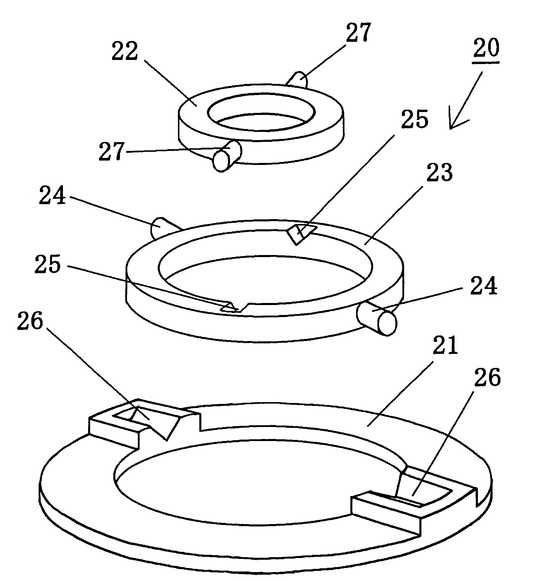
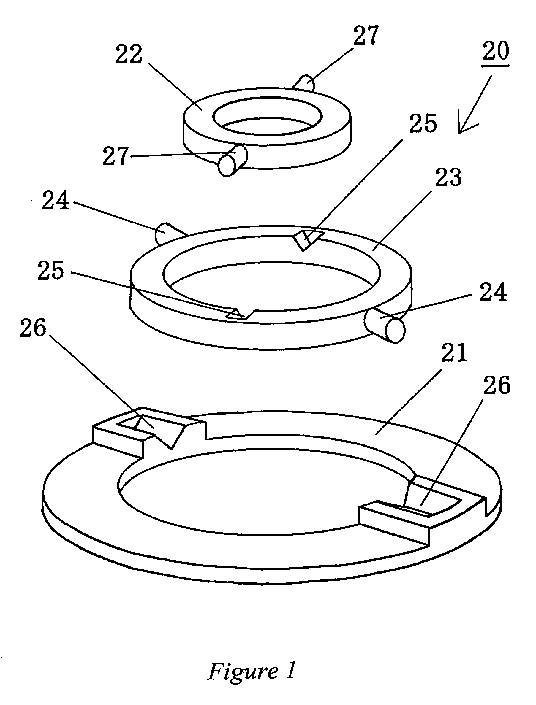
[0031]Embodiments of the present invention will now be described hereinafter in detail with reference with the accompanying drawings. FIG. 1 is a perspective view of the respective subcomponents of a coupling 20. These subcomponents include a first coupling ring 21, a second coupling ring 22, and a third coupling ring 23. The third coupling ring 23 is of a ring shape (a portion of a cylinder) and includes a pair of connecting projections 24 disposed on an outer circumferential surface of the third coupling ring 23, at diametrically opposed positions along a first diameter. Facing an inner portion of the third coupling ring 23, at diametrically opposed positions are v-grooves 25. The grooves 25 are positioned along a second diameter, which is perpendicular to the first diameter. Although the grooves (v-shaped grooves) 25 are shown as v-shaped, flat or U-shaped grooves are examples of other acceptably-shaped grooves as well. Other shapes may be used as well, where the design considera...


PUM


Abstract

A coupling includes a first coupling member, a second coupling member, and a third coupling member being located in between the first coupling member and the second coupling member. The third coupling member has formed thereon a first pair of connecting elements diametrically opposed to one another and defining a first axis, and further has formed thereon a second pair of connecting elements diametrically opposed to one another and defining a second axis that is substantially perpendicular to the first axis. The first coupling member has formed thereon a third pair of connecting elements configured to conform to the first pair of connecting elements of the third coupling member. Formed on the second coupling member is a fourth pair of connecting elements configured to conform to the second pair of connecting elements of the third coupling member.

Description

CROSS-REFERENCE TO RELATED PATENT APPLICATIONS[0001]The present application claims priority to U.S. provisional patent application Ser. No. 60 / 469,822, which contains subject matter related to that disclosed in U.S. patent application Ser. No. 10 / 336,991, filed Jan. 6, 2003, entitled “Rotation Sensor” and now issued as U.S. Pat. No. 6,715,368 B1; U.S. patent application Ser. No. 10 / 316,442, filed on Dec. 11, 2002, entitled “Rotation Sensor” and now issued as U.S. Pat. No. 6,725,734 B1; Japanese Patent Application No. 2002-299218, filed in the Japanese Patent Office on Oct. 11, 2002; and Japanese Patent Application No. 2002-14185, filed in the Japanese Patent Office on Jan. 23, 2002, the entire contents of each of which being incorporated herein by reference.BACKGROUND OF THE INVENTION[0002]1. Field of the Invention[0003]The present invention relates to rotation sensors and couplings used in rotation sensors, where such rotation sensors may be used as an automotive rotation sensor fo...

Claims


Application Information

Patent Timeline
Patent Type & Authority Patents(United States)
IPC IPC(8): G01L3/00G01N3/02G01D5/245B62D5/04B62D5/06B62D6/10B62D15/02F16D3/26F16D3/42F16D7/06G01D5/347
CPCB62D6/10B62D15/0215G01D5/34738F16D3/42F16D3/26
Inventor SUGIYAMA, SATOSHI
Owner FURUKAWA ELECTRIC CO LTD
Why Eureka
Try Eureka